MediaRecorder 6.5 - Reference manual
- Welcome to MediaRecorder
- Welcome to MediaRecorder
- Introduction
- What’s new in MediaRecorder 6.5
- What’s new compared to version 6.2
- What's new compared to version 6.0
- What’s new compared to version 5
- End-User Licence Agreement
- System Requirements
- Specifications
- System requirements
- Requirements of a custom computer
- Test an unsupported setup
- Supported devices
- Video formats
- Installation
- Installation
- The steps to install MediaRecorder
- Turn off automatic updates for device drivers
- Select correct power options
- Install MediaRecorder and device drivers
- Activate your MediaRecorder license
- End-User Licence Agreement
- Acknowledgments and copyright notices
- Upgrade to MediaRecorder 6.5
- Upgrade MediaRecorder
- Upgrade your MediaRecorder license to continue working with your hardware key
- Upgrade recording devices
- Recording Devices
- Recording devices
- Analog cameras
- IP cameras
- USB devices
- Important notes about USB
- GigE Vision cameras
- Screen capture devices
- Use of the Screen Capture tool
- Epiphan screen capture devices
- Recording video
- Record video
- To get started
- Select a video device
- Select an audio device
- Video file options
- Change the video file location
- Set video file base name
- Select or deselect videos for recording
- Record your videos
- Mute audio in preview
- Options
- Change video order in preview
- Show frame rate, resolution and format
- Refresh the preview
- See which preview image comes from which camera
- Show or hide recording properties
- Save the camera settings
- Pan, Tilt, Zoom control with IP cameras
- Enter a default user name and password of IP cameras
- Use commands
- Picture by Picture resolution
- MediaRecorder with The Observer XT
- MediaRecorder with The Observer XT
- How to record videos for The Observer XT
- MediaRecorder with The Observer XT
- Create exceptions for N-Linx port in Windows Firewall
- Make sure The Observer XT can access the MediaRecorder video files
- Install N-Linx Agent
- Create MediaRecorder Settings
- Create The Observer XT settings
- Carry out an observation in The Observer XT
- Troubleshooting
- Synchronize videos with events
- View the automatic offset of videos imported into The Observer XT
- Synchronize manually
- MediaRecorder with EthoVision XT
- MediaRecorder with EthoVision XT
- First create videos in MediaRecorder and then track from video file in EthoVision XT
- Control video recording by MediaRecorder with EthoVision XT when you track live
- Adjust the video aspect ratio (analog cameras only)
- MediaRecorder with FaceReader
- Troubleshooting
- Record at a predefined time
- Set up Analog cameras
- Set up analog cameras
- Install the Picolo Alert PCIe card
- Install the drivers for the Picolo Alert card
- Connect the analog camera to the computer
- Change video standard
- Set up IP cameras
- Set up IP cameras
- The steps to install IP cameras
- Ethernet card setup
- Install the Ethernet card
- Set Ethernet card IP address
- Connect IP cameras to the PC
- Camera setup
- Set camera IP address
- Set camera password and select power line frequency
- Create camera settings
- Create audio settings
- Select ONVIF cameras in MediaRecorder
- Adjust advanced video quality options
- Select devices that do not support ONVIF in MediaRecorder
- Set up GigE cameras
- Set up GigE cameras
- The steps to install GigE cameras
- Connect the GigE cameras to the PC
- Install MediaRecorder with the camera drivers
- Set camera IP address
- Configure the cameras
- Set up the Epiphan Pearl Nano screen capture device
- Set up USB 3 cameras
- Set up USB 3 cameras
- The steps to install USB 3 cameras
- Install the USB 3 interface card
- Install the USB 3 camera driver
- Connect the USB 3 cameras to the PC
- Configure the Basler USB 3 camera
- Audio devices
- Summary supported devices
Welcome to MediaRecorder
Welcome to MediaRecorder

Main topics
What's new compared to version 6.2
How to use this Help?
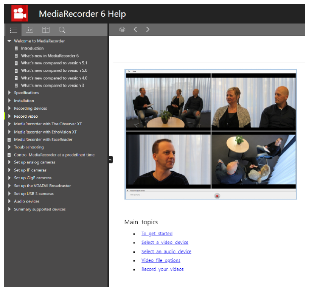
TIPS
- To use the Help at its best, set Internet Explorer, FireFox, Google Chrome or a similar browser, not Microsoft Edge, as the default browser.
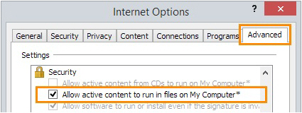
- If you keep getting the message “Internet Explorer restricted this webpage...”, do the following: in Internet Explorer, choose Tools > Internet Options > Advanced. Under Security, select Allow active content to run in files on My Computer. Click OK, then close and restart the Help.
- If you do not see the Table of Contents on the left, enlarge the Help window or zoom out (Ctrl+mouse wheel, or Ctrl+-).
- To search for two or more adjacent words, use quotation marks, for example “Action Unit”.
- To go back to the search results after visiting one of the result pages, click again on the magnifying glass icon in the Search field.

Introduction
MediaRecorder is a software package that makes digital video files with input of many different types of cameras. These video files can be used in the video analysis programs The Observer XT, EthoVision XT and FaceReader.
Supported video devices
MediaRecorder is supported with several types of video devices. In the section on the type of device, you find which specific devices are tested and supported, how many devices you can use simultaneously, at what frame rate and resolution and in which Noldus software.
MediaRecorder is supported with the following devices types.
We recommend to create a test recording with your devices first before you carry out the actual recordings, especially when you have more or other devices than we officially support.
See Record video.
Modules
MediaRecorder has the following modules.
- Base Module – To record up to four video files simultaneously. However this number depends on the type of video device, since multiple cameras are not supported for all devices. See the section on your device how many devices are supported at what frame rate and resolution.
- Additional Camera Module 1-6 camera – For analog, or IP cameras only. To extend the number of cameras to 6.
- Additional Camera Module 1-8 cameras – For IP cameras only. To extend the number of cameras to 8.
Standalone or with other software
MediaRecorder can be used as a standalone program to create video files. It is also possible to use the Noldus network communication protocol N-Linx, to use it in combination with The Observer XT. This way, recording with MediaRecorder starts automatically when starting an observation in The Observer XT and stops when this observation is ended. Furthermore, the videos obtained this way are automatically linked to an observation and synchronized with the manually scored events.
It is also possible to control recording with commands from EthoVision XT, for example to start recording when a mouse leaves the shelter.
MediaRecorder Help
This Help describes how to use MediaRecorder 6.5 with the supported recording devices. Information about devices from companies other than Noldus IT is valid at the moment of the release and may change afterwards without our knowledge.
If you have any problems, questions, remarks or comments, please let us know.
See Support in Troubleshooting for contact information.
What’s new in MediaRecorder 6.5
If you have been using a previous version of MediaRecorder, you should read these topics to get an idea of the improvements in this version.
- What's new compared to version 6.2
- What’s new compared to version 6.0
- What’s new compared to version 5
What’s new compared to version 6.2
Selection of audio source for all the videos
While previously only Audio device 1 could be used as a common audio source for all the videos, now in Picture-in-Picture mode, you may select which audio source to use for this purpose.
Data Transparency Policy
When starting recording, a pop-up window will appear, informing you about Noldus's Data Transparency Policy.
If you have been using a previous version of MediaRecorder, you should read these topics to get an idea of the improvements in this version.
What's new compared to version 6.0
Software activation code instead of hardware key
MediaRecorder 6.2 comes with a software activation code as the license which makes it easier to work with the software. For existing customers it is still possible to upgrade their hardware key.
What’s new compared to version 5
Output quality selection
Instead of using the default output quality you can now select optimized settings for when you are using your recorded video files in (1) a four-camera EthoVision set-up; (2) a DanioVision set-up or (3) with the Remote Photo Plethysmography module in FaceReader. See Output settings for more information.
Recording with a frame rate of 1 fps
It is now possible to select a frame rate as low as 1 fps when filming slowly-moving subjects.
Prevent black frames at the start of your videos
With the default settings of MediaRecorder there may be black frames at the start of your videos. If that is the case EthoVision will not automatically start tracking and FaceReader will not start analyzing from the start of your videos. You can now edit the VsSettings file that comes with MediaRecorder to prevent black frames. For more information see Prevent black frames at the start of your videos.
Euresys Picolo H264 boards not supported
The Picolo U4 and U8 H264 boards are end of life and only have 32 bit drivers. Therefore the latest version of MediaRecorder does not support them anymore.
End-User Licence Agreement
Revised: 21 July 2022
END-USER LICENSE AGREEMENT
IMPORTANT – READ CAREFULLY. Please read this End-User License Agreement ("EULA" or “Agreement”) carefully before checking the “accept” checkbox, downloading or using the Software (as defined below). By checking the “accept” checkbox, downloading, installing or otherwise using the Software, End-User agrees to be bound by the terms and conditions of this EULA. If you do not agree to the terms and conditions of this EULA, do not check the “accept” checkbox and do not download, install or use the Software.
The Software is protected by copyright laws and international copyright treaties, as well as other intellectual property laws and treaties. The Software is licensed, not sold.
1. DEFINITIONS
Terms used in this EULA but not otherwise defined shall have the meaning assigned to them below:
1.2. End-User: the individual or legal entity that has acquired or uses the Software under the terms and conditions of this EULA.
1.3. EULA: this End-User License Agreement.
1.4. Indirect Losses: any indirect loss, claim, damage, liability, or expenses (including reasonable attorney's fees), including lost profits, and damage due to the stagnation of business operations.
1.5. Network License: a licensing mechanism comprising a license file and accompanying software managing the number of concurrent users of the Software.
1.6. Noldus: Noldus Information Technology BV, with registered office at Nieuwe Kanaal 5, 6709 PA Wageningen, The Netherlands, listed in the Trade Register under Chamber of Commerce number 09094422, or its subsidiaries listed in the document https://www.noldus.com/legal/noldus_corporate.pdf.
1.7. Security System: a system of software protection to limit installation and use of the Software to the authorized End-Users and computers.
1.8. Security Device: a device that forms part of or is attached to the computer, and is used as part of the Security System to control access to the Software.
1.9. Software: the software (including, but not limited to, any updates, upgrades and associated media, printed or electronic documentation and online services) provided to the End-User by Noldus or an Authorized Partner together with this EULA, that is not covered by third party terms and conditions and is included in the list under “Noldus software” in the Annex to the General Terms and Conditions (https://www.noldus.com/legal/noldus_gtc.pdf).
2. LICENSE
2.1. Upon payment by the End-User of the license fees for the Software, Noldus grants End-User a revocable, non-exclusive license to download, install and use the Software in accordance with the terms and conditions of this EULA. This EULA does not grant any rights to obtaining future upgrades, updates or supplements of the Software. If upgrades, updates or supplements of the Software are obtained, however, the use of such upgrades or updates is governed by this EULA and the amendments that may accompany them and may be subject to additional payments and conditions.
2.2. The End-User may download, install and use the Software on as many computers as is reasonably necessary, however the Software may not be shared or used concurrently on more computers than for which EULA’s are granted. End-User shall take all reasonably required steps to ensure that this number is not exceeded.
2.3. End-User is allowed to store or install a copy of the Software for back-up or archival purposes.
2.4. End-User shall not (i) modify, alter, adapt, merge, decompile or reverse-engineer the Software or any part thereof nor create any derivative works based on all or any part of the Software, or (ii) remove or obscure any copyright, trademark or other ownership notices from the Software, or (iii) sub-license, sell, rent, lease, hire, loan, assign or otherwise transfer the Software or your rights in the Software or any part thereof, except as provided for in this EULA.
2.5. The Software may be protected by a Security System, including but not limited to the use of expiry dates, time-limited or feature-limited licenses, authorization codes, Security Devices and Network Licensing. End-User is prohibited to (attempt to) remove, alter or circumvent in any way any part of such Security System.
2.6. End-User is responsible for regular, frequent and effective backups of all files produced or modified while working with the Software.
3. INTELLECTUAL PROPERTY
3.1. All title, copyright and other industrial, intellectual or proprietary rights in and to the Software (including but not limited to any images, photographs, animations, video, audio, music, and text incorporated into the Software), the accompanying printed materials, and any copies of the Software are owned by Noldus or its Authorized Partners. All rights not expressly granted are reserved by Noldus.
3.2. The Software may include or make use of third party software, including open source software. Such third party software may be subject to the third party’s terms and conditions provided in the documentation accompanying the Software and may contain copyright or other industrial, intellectual or proprietary rights of such third party. End-User hereby agrees to the terms and conditions for such third party software. In the absence of any third party terms and conditions, this EULA will govern the third party software in the Software.
3.3. End-User may, from time to time, provide Noldus with comments, suggestions, data, information or feedback (“Feedback”) on the Software. End-User acknowledges and agrees that such Feedback may be freely used by Noldus, at its sole discretion, for the design, development, improvement, marketing and commercialization of its products and services, without any restrictions based on confidentiality or intellectual property rights.
4. TRANSFER
4.1. End-User is entitled to make a one-time, permanent transfer of this EULA and Software only directly to one other End-User. This transfer must include all of the Software (including all component parts, the media and printed materials, any upgrades and this EULA). Such transfer may not be by way of consignment or any other indirect transfer and shall be subject to the following provisions:
a. End-User will provide to Noldus prior to any such transfer the full name and address details of the new End-User and the expected date of transfer in writing;
b. The new End-User understands and agrees to all the terms and conditions of this EULA in the same way as if the new End-User had obtained the Software from Noldus or an Authorized Partner;
c. End-User will destroy all (partial) copies of the Software and all accompanying materials, including but not limited to installed copies and any backup copies on data storage devices and guarantee to Noldus in writing that this has been done. If the Software is an upgrade, any transfer must include all prior versions of the Software;
d. Noldus reserves the right to levy an administrative charge upon the End-User and/or the new End-User in relation to transfer of the Software to an End-User
4.2. Any attempted transfer without prior written permission from Noldus shall constitute a material breach of this Agreement and shall be deemed null and void.
5. TERM; TERMINATION
5.1. The EULA shall enter into force on the date of acceptance by the End-User and continue until terminated in accordance with this Section 5.
5.2. If the Software is licensed on a subscription basis, the EULA shall continue until the end of the current subscription period.
5.3. Noldus is entitled to terminate the EULA immediately upon prior written notice upon:
a. the breach of any material provision of this Agreement by the End-User if (i) such breach is not curable or (ii) if curable, the End-User has not cured such breach within 30 (thirty) day period following receipt of a written notice by Noldus substantiating such breach ("ingebrekestelling");
b. the filing or institution of bankruptcy, liquidation or receivership proceedings of the End-User or in the event a receiver or custodian is appointed for the End-User’s business, or if its business is discontinued or if it has a petition presented by a creditor for its winding up or if the End-User enters into any liquidation (other than for purpose of reconstruction or amalgamation.
5.4. Upon termination of the EULA, the End-User shall immediately discontinue the use of the Software and remove the software of all computers, destroy all (partial) copies of the Software from all storage media and return the documentation and materials relating to the Software to Noldus or its Authorized Partner.
5.5. Termination of this Agreement does not remove or reduce End-User’s obligation to pay any outstanding license fees or other monies, all of which shall be due for payment immediately on termination of the EULA.
5.6. The following provisions shall survive termination of this EULA: Sections 3, 7, 9, 10 and this Section 5.6. In addition, any other provisions which are required to interpret and enforce the Parties' rights and obligations under the EULA shall also survive any termination or expiration of this EULA, but only to the extent required for the full observation and performance of the EULA.
6. WARRANTY
6.1. Noldus warrants that the Software as of the date of delivery to the End-User by Noldus or its Authorized Partner, the Software will, for a period of 90 days (“Warranty Period”) materially conform to the specifications set out in the user documentation accompanying the Software (“Specifications”), provided that:
a. the Software is properly installed on a supported computer platform (as defined in documents that can be accessed on https://my.noldus.com) and used in accordance with the provisions of the accompanying user documentation and/or any Noldus-approved training course;
b. Noldus is notified in writing within 14 days after any non-conformity of the Software was known or should reasonably have been known to End-User and the End-User has made available all the information that might reasonably be required to allow Noldus to investigate, recreate and where possible remedy a non-conformity;
c. the Software has not been (a) altered, repaired or modified by any party other than Noldus or a third party provider approved by Noldus; or (b) used with software or a computer platform other than set out in the documents that can be accessed on https://my.noldus.com or have been subjected to negligence, or computer or electrical malfunction; or (c) were used, adjusted, or installed other than in accordance with instructions by Noldus.
6.2. Other than set out in Section 6.1, no warranties are expressed or implied with respect Software or any element thereof, including without limitation its quality, performance, accuracy, merchantability or suitability or fitness for any purpose, whether or not that purpose has been communicated by End-User to Noldus. The Software is a general product developed by Noldus for a wide range of solutions, requirements and situations and End-User is responsible for purchasing
the Software required for his needs. Noldus explicitly does not warrant that the Software shall be entirely without error or fault nor that it will operate without interruption. End-User agrees that such errors, faults or interruptions shall not be deemed material and cause to terminate this EULA.
6.3. The warranty by Noldus set out in Section 6.1 applies only to the first installation of the Software and will not apply, resume or renew upon delivery or installation of any subsequent update or upgrade to the Software, alteration in the number of EULA’s granted for use of the Software, or any other extensions, upgrades or alterations to the Software where the Software has previously been delivered to or installed by the End-User.
6.4. The warranty by Noldus set out in Section 6.1 shall further not apply to Software that is licensed or otherwise made available at no cost, or Software that is designated as ‘prototype’, ‘alpha’ or ‘beta’ code, all of which are provided ‘as is’ and without warranty, representation or liability.
6.5. Upon receipt of an End-User’s written notice of the Software not conforming to the Specifications during the Warranty Period, Noldus shall at its option and in its sole discretion (i) assist the Customer in correcting or replacing the non-conforming Software or, (ii) terminate the EULA immediately and refund the purchase price paid by the End-User. The remedies described above shall be End-User’s sole and exclusive remedies. Upon expiration of the Warranty Period, Noldus shall have no obligation to provide such remedies.
6.6. Noldus and Authorized Partners, are not responsible for maintaining or supporting use of the Software or obligated to provide any updates, fixes or support to the Software unless otherwise expressly agreed in writing between End-User and Noldus or the Authorized Partners.
7. LIABILITY; INDEMNIFICATION
7.1. End-User acknowledges that the Software is intended for research or training purposes only and agrees not to use the Software for diagnosis or treatment of disease in human subjects. End-User agrees not to use the Software in any application where the failure, malfunction or inaccuracy of the Software carries the risk of death or bodily injury.
7.2. Noldus Software shall not be used for collection of biometric data from human subjects without prior informed consent from the person whose data is being captured.
7.3. Noldus does not allow the use of its Software for the following applications:
a. Active defense, i.e. embedding Noldus Software in a weapon system.
b. Biometric data collection in criminal, security-related or similar investigations or procedures.
c. Surveillance of people in public spaces for security purposes.
d. Any other use that may potentially violate fundamental human rights (https://www.un.org/en/about-us/universal-declaration-of-human-rights).
7.4. If Noldus notices that its Software is used for applications that it does not approve, this may lead to discontinuation of customer support and termination of the EULA.
7.5. To the fullest extent permitted by law, and not withstanding any other provision of this EULA to the contrary:
a. In no event will Noldus or the Authorized Partners be liable to the End-User for Indirect Losses or for special, incidental, consequential, exemplary, enhanced, or punitive damages, including without limitation, any damages resulting from interruption of business, loss of use, loss of profits or revenue, or loss of business, arising out of or in connection with this EULA, the Software, or the performance of Noldus, the Authorized Partners, or third parties engaged by Noldus in the performance of this EULA, regardless of whether Noldus, the Authorized Partners, End-User, or any other person or entity has been advised of (or could have reasonably foreseen) the possibility of such damages or Indirect Losses. If, despite the provisions in this EULA, liability exists anyway, only direct damage will be eligible for reimbursement
INTELLECTUAL PROPERTY INFRINGEMENT CLAIMS.
7.6. Noldus’ and Authorized Partners’ liability shall also be excluded, and Noldus and the Authorized Partners shall not have any liability under this EULA in the event of:
a. End-User’s use of the Software other than in accordance with Section 7.1;
b. in the event of direct and indirect consequences of the End-User’s failing to adhere strictly to the user documentation provided or made available by Noldus or the Authorized Partner; or
c. any loss of or damage to files or data howsoever caused.
7.7. A liability claim will be unenforceable and lapse unless Noldus or the Authorized Partner receives a written notice thereof no later than 6 months after the discovery of an event or circumstance that gives or may give rise to that claim.
7.8. Noldus will hold harmless, defend, and indemnify End‐User from and against all losses, damages, claims, liabilities, and expenses incurred by End‐User that arise out of, relate to, or are caused by any third party claim that End‐User’s use of the Software, pursuant to the terms of the this EULA, infringes the intellectual property rights of such third party. If such a claim is made or appears likely to be made, Noldus, at its option, will have the right to either (i) procure for the End‐User the right to continue to use the Software, (ii) modify or replace the Software so that it is no longer infringing (in a manner that substantially retains its functionality and quality), or (iii) require End‐User to terminate the use of and return the Software and refund a pro rata portion, if any, of the amount paid by End‐User to Noldus for the infringing Software. Notwithstanding the foregoing, Noldus will have no liability to End‐User if the infringement results from use of the Software in combination with software not provided by Noldus or from modifications made by Noldus to conform to specifications provided by End‐User. The indemnification obligations in this section are subject to: (i) End‐User giving Noldus prompt written notice of any claim (provided that End‐User's failure to provide prompt written notice will only relieve Noldus of its obligations under this Section to the extent such failure materially limits or prejudices Noldus’ ability to defend or settle such claim); (ii) the transfer of sole control of the defense and any related settlement negotiations to Noldus; and (iii) End‐User's cooperation, at Noldus’ expense, in the defense of such claim. THIS SECTION STATES END‐USER'S SOLE AND EXCLUSIVE REMEDIES FOR THIRD PARTY INTELLECTUAL PROPERTY INFRINGEMENT CLAIMS.
7.9. End-User shall indemnify and hold harmless Noldus, the Authorized Partners, and the third parties engaged by Noldus from and against any and all losses (including Indirect Losses and special, incidental, consequential, exemplary, enhanced, or punitive damages) arising out of or caused by (i) any failure in the performance of the obligations of the End-User under the law, this EULA, or Noldus’ General Terms and Conditions, or (ii) any and all third party claims on any grounds whatsoever, directly or indirectly related to the End-User’s use of the Software, the contents thereof, or any results or materials generated by the Software.
7.10. THE LIMITATION OF LIABILITY PROVISIONS SET FORTH IN THIS SECTION 7 SHALL APPLY EVEN IF END-USER’S REMEDIES UNDER THIS EULA FAIL OF THEIR ESSENTIAL PURPOSE.
7.11. Noldus and End-User acknowledge and agree that the parties entered into this EULA in reliance upon the limitations of liability set forth in this Section 7, that the same reflect an allocation of risk between the parties (including the risk that a contract remedy may fail of its essential purpose and cause consequential loss), and that the same form an essential basis of the bargain between the parties.
8.MISCELLANEOUS
8.1. Parties may communicate with each other by electronic mail. Parties recognize the risks associated with electronic mail and declare that they shall not hold each other liable for any damage incurred by either of them as a result of the use of electronic mail. If a Party is in doubt as to the content of an electronic message received, the content of the message originating with the sender shall be decisive.
8.2. The invalidity or unenforceability of any provision this EULA shall not affect or limit the validity or enforceability of any other provisions thereof. Any such invalid or unenforceable provision shall be deemed
to be substituted by a provision that is considered to be valid and enforceable. The interpretation of the substituting provision shall be as close as possible to the economic, legal and commercial objectives of the severed provision.
8.3. Failure by Noldus or the Authorized Partner to enforce any of its rights under the EULA shall not constitute a waiver of such rights thereunder and shall not relieve End-User of its obligation to comply with such provisions. No waiver or amendment of any provisions therein shall be effective unless signed in writing by a Noldus representative. Any such written waiver shall only be applicable to the specific instance to which it relates and shall not be deemed to be a continuing or future waiver.
8.4. Amendments or changes to this EULA can only be agreed upon in writing between the Parties.
8.5. The EULA shall be binding upon the Parties thereto, their legal representatives, successors and assigns. End-User shall not assign any right or obligation arising out of this EULA without the prior written consent of Noldus. Any attempt by End-User to assign or delegate any obligation hereunder shall be deemed null and void.
9.GOVERNING LAW: END-USERS USA OR CANADA
9.1. If End-User is a legal entity and its principal place of business is located in the United States of America or Canada, or if End-User is an individual whose primary residence is located in the United States of America or Canada:
a. This EULA is exclusively governed by the laws of the Commonwealth of Virginia and the applicable federal laws of the United States of America, without regard to the conflicts of law provisions of any jurisdiction. Without limiting the previous sentence, End-User and Noldus expressly agree: (i) that the Virginia Uniform Computer Information Transactions Act, Virginia Code §§ 59.1-501.1 et seq. (“UCITA”), and the United Nations Convention on Contracts for the International Sale of Goods (“CISG”) are expressly excluded from this EULA, (ii) that any and all terms contained in UCITA or CISG will have no force or effect on any portion of this EULA, and (iii) that UCITA and CISG do not apply to this EULA or the Software.
b. Any and all claims and disputes arising out of or in connection with this EULA, the Software, or the performance or non-performance by either party of any of its obligations under this EULA, which End-User and Noldus cannot resolve amicably within a reasonable period of time, will be commenced and maintained only in a state or federal court of competent subject matter jurisdiction situated or located in the United States of America. Noldus and End-User consent to the exclusive personal jurisdiction of and venue in any such court.
c. To the extent permitted by law: End-User must commence or file any claim or action arising out of or relating to this EULA or the Software within six months after the cause of action accrues, otherwise, such claim or cause of action is permanently barred. To the extent permitted by law, End-User expressly waives the right to commence or file any such claim or action under any longer statute of limitations.
10.GOVERNING LAW: END-USERS OTHER COUNTRIES
10.1. If End-User is a legal entity and its principal place of business is located in any country other than the United States of America or Canada, or if End-User is an individual whose primary residence is located in any country other than the United States of America or Canada:
a. This EULA is exclusively governed by the laws of The Netherlands. The United National Convention for Contracts on the International Sale of Goods is expressly excluded.
b. Any disputes arising out or in connection with this EULA that cannot be solved amicably within a reasonable period of time will be submitted to the competent court in Arnhem, The Netherlands, for any dispute with End-Users having their principal place of business in the European Union. In the event that an End-User has its principal place of business outside the European Union, the United States of America or Canada, any dispute shall be finally settled in accordance with the Arbitration Rules of the Netherlands
Noldus Information Technology – End-User License Agreement Revised: 21 July 2022 – Page 4 of 4
Arbitration Institute. Location shall be Arnhem, The Netherlands. The arbitration procedure shall be conducted by one (1) arbiter in the English language.
System Requirements
Specifications

Main topics
System requirements
Operating system
MediaRecorder 6 supports Windows 11 64 bit Professional edition.
Language packs
MediaRecorder 6.5 was thoroughly tested with the Windows 11 U.S. English language packs. It is possible that certain local language versions of Windows may affect the performance of the program.
Touch features
MediaRecorder is not designed for use with Windows touch features.
Computer
Desktop computer
MediaRecorder 6.5 has been tested with a Dell Precision™ T3640 and 5820 PC. If you order a complete solution from Noldus Information Technology, you will obtain one of these computers, or a successor, with MediaRecorder installed and ready to use.
Laptop
MediaRecorder 6.5 has been tested on a Dell Precision™ 3551 mobile workstation with the following devices only:
- 2 Axis P1375 cameras (Portable Observation Lab). For more information on the Portable Observation Lab, consult the Reference Manual on the desktop of the notebook.
- 1 Axis P1375 camera and 1 Epiphan Pearl Nano (Portable Usability Lab). For more information on the Portable Usability Lab, consult the Reference Manual on the desktop of the notebook.
- 1 Basler acA1920-155um USB 3.0 camera.
Technical specifications test computers
Dell Precision™ T3640 PC
- Processor: Intel i7-10700, 4.8 GHz.
- Internal memory: 8 GB.
- Hard disk: 1 TB.
- Graphics card: 5 GB NVIDA Quadro P2200.
Dell Precision 5820
- Processor: Intel i9-10900X CPU @3.70 GHz
- Installed RAM: 8.00 GB
- Graphics card: Nvidia Quadro Pro P2200
Dell Precision™ 3551 mobile workstation
- Processor: I7-10750H (6-core), 2.2 GHz.
- Internal memory: 8 GB.
- Graphics card: 4 GB Nvidia Quadro P620 w.
- Hard disk: 1TB.
Requirements of a custom computer
Before purchasing a new computer
We recommend that you use the Dell Precision T3640 or T5820 desktop computer. For the devices that are supported on a laptop (See Laptop), we recommend the Dell Precision 3551 mobile workstation.
If you are planning to purchase a different computer, please contact us for detailed advice.
Computer requirements
- For working with MediaRecorder and video (files or cameras), we recommend that you use a professional workstation. It is possible to buy consumer-range computers with a high processor speed and plenty of memory, but in order to remain competitive regarding price, the manufacturers often economize on the underlying system architecture. That means those computers are suitable for home use, but not for running professional scientific software. You should select a computer which is intended for professional use or labeled by the manufacturer as a workstation.
- If you use an older desktop computer, it should have at least a 2.8 GHz Quad Core processor and at least 4 GB of memory. A laptop should have at least a 2.6 GHz Quad Core processor and at least 4 GB of memory.
- You need sufficient free disk space to store the video files (MPEG-4 at least 0.5 GB/hr, and H.264 at least 0.6 GB/hr).
- For working with digital video, a good quality high-end video card designed for workstations is recommended.
- We recommend to use a separate 1 Gb network adapter for the IP and GigE cameras and the Epiphan Pearl Nano and preferably the Intel Pro/1000 CT or PT. For multiple GigE cameras, you need a separate network adapter for each camera.
Test an unsupported setup
Aim
To test the quality of MediaRecorder videos with an unsupported camera or computer.
Background
When using an unsupported setup, the following problems may occur:
- Video frames are dropped, resulting in incorrect video lengths.
- The audio and video are not synchronous.
- Two or more video streams are not synchronous.
Procedure
- Set a timer display running on a computer monitor (preferably with both digital and analog display) and play music (not on the same computer as MediaRecorder). Make sure no background programs are running on the computer.
- Make a recording in the normal way. Remember to plug in your microphone if you plan to use audio.
- After the normal maximum recording time, give an audio and visual cue (e.g. click your fingers) and stop the recording
- Check the recording length in MediaInfo and number of frames in GSpot. Use the frame rate to determine if any frames are dropped.
See Tools for troubleshooting - Go to the moment where you gave the cue and check if the audio and video are in sync, and if multiple videos are in sync.
Whether a small error (one that normally tends to occur) is to be considered a problem or not depends entirely on the required level of accuracy of the audio and video recording.
Supported devices
Tested devices
The latest version of MediaRecorder has extensively been tested with the following devices:
IP cameras
- Axis P1375
- Axis M5525
- Axis M1075-L
Screen capture devices
- Epiphan Pearl Nano
Earlier versions of MediaRecorder have been tested with the following devices:
Analog cameras
PhenoTyper Top Unit camera (EIA and CCIR) in combination with
- the Euresys Picolo Alert PCIe
IP cameras
- Axis P5512
- Axis P5514
- Axis P5515
- Axis P5534
- Axis M1054
- Axis M1065-L
- Hikvision IP DS-2PT7D20IW-DE
USB cameras
- Basler acA1920-155um USB 3.0 camera
- Basler acA2040-90uc
- Logitech BRIO USB 3.0 camera
FireWire camera
- The Imaging Source DMK 21AF04 for the DanioVision system with FireWire camera.
GigE camera
- Basler acA1300-60gm monochrome camera.
Screen capture devices
- Epiphan DVI2USB 3.0.
- Epiphan VGADVI broadcaster.
- The MR Screen Capture Module.
Combinations of devices
- Portable Observation Lab version 6 (two Logitech BRIO USB 3.0 cameras).
- Portable Observation Lab version 5 (two Axis M1065 IP cameras).
- Portable Usability Lab version 5 (one Logitech BRIO USB 3.0 camera and one Epiphan DVI2USB 3.0 screen capture device).
- Stationary Usability Lab (three IP cameras and one Epiphan VGADVI broadcaster).
Keyboard
CH products RS Desktop joystick for Pan, Tilt, and Zoom control of IP cameras.
Video formats
Formats of video file created by MediaRecorder
The video format MediaRecorder creates, depends on the input:
- PhenoTyper Top Unit camera - Video files in H.264 AVC in an MPG container.
- IP cameras – Video files in H.264 AVC with audio in AAC in an MP4 container.
- Other digital cameras – Video files in MPEG-4 DivX with audio in AAC in an MP4 container.
- Picture in Picture, or Picture by Picture; all video formats – Video files in MPEG-4 DivX with audio in AAC in an MP4 container. See Video file options in Record video for more information on the options Picture in Picture and Picture by Picture.
Background information
MPEG-4 DivX
MPEG-4 can achieve a high rate of compression with good quality, because it separately codes the background (which does not change much from frame to frame) from the moving parts of the video. MPEG-4 is in fact best seen as a collection of definitions rather than one fixed file format, and there are many different implementations of MPEG-4. MPEG-4 has a higher compression rate than for example MPEG-2 and it can have much higher resolution (with MediaRecorder up to 1920 x 1280 pixels).
MediaRecorder creates MPEG-4 DivX video files from several digital recording devices (see above). DivX is an implementation of MPEG-4 which has both high quality and good compression. MPEG-4 DivX decoding software for playing back the video files is installed with MediaRecorder.
H.264 AVC
H.264 AVC is a type of MPEG-4 and is also known under the names H.264/AVC, AVC/H.264, H.264/MPEG-4 AVC, MPEG-4/H.264 AVC, MPEG-4 Part 10 or x.264. It creates good video quality and uses previously-encoded pictures as references in a much more flexible way than in other standards, allowing the use of up to 16 reference frames. MediaRecorder creates H.264 AVC video files from output of analog and IP cameras (see above). H.264 decoding software for playing back the video files is installed with MediaRecorder.
Note
On computers with Windows 10, some Windows Media Player codecs need to be disabled to be able to play back the H.264 video files with an MPG container which MediaRecorder creates from PhenoTyper Top Unit camera. These codecs are disabled by MediaRecorder installation. De-installing MediaRecorder restores the Windows Media Player codecs. Contact Noldus Support if you want to play back the videos from PhenoTyper Top Unit camera on another computer than the one with MediaRecorder.
Installation
Installation
Main topics
- The steps to install MediaRecorder
- Turn off automatic updates for device drivers
- Install MediaRecorder and device drivers
- Activate your MediaRecorder license
- Upgrade to MediaRecorder 6.5
The steps to install MediaRecorder
IMPORTANT
If you have an older version of MediaRecorder - Uninstall MediaRecorder 6.0 and older versions before you install MediaRecorder 6.5.
If you have a hardware key - Do not insert your key before the installation is complete. If you do so, other drivers are automatically installed, which may lead to incorrect functioning of the license key. Drivers of the license key should be installed using the installation USB stick.
See Install MediaRecorder and device drivers
Procedure
- Turn off automatic updates for device drivers
- Select correct power options
- Install MediaRecorder and device drivers
Turn off automatic updates for device drivers
Aim
To make sure the devices use the drivers that were tested with MediaRecorder.
Background information
The general recommendation from Microsoft to use automatic updates is good, especially for security updates. However, automatic updates of hardware device drives can sometimes give problems. MediaRecorder is tested with the device drivers that are available at the moment of the release. If device drivers are updated afterwards, we cannot guarantee that they will work properly with MediaRecorder. Therefore we recommend to switch off automatic updates of device drivers.
If you ordered a computer with MediaRecorder from Noldus IT, the automatic updates for device drivers have already been turned off and you can skip this topic.
Procedure
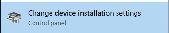
- Open the Start window and type Change Device Installation Settings.
- Click the tile that appears.

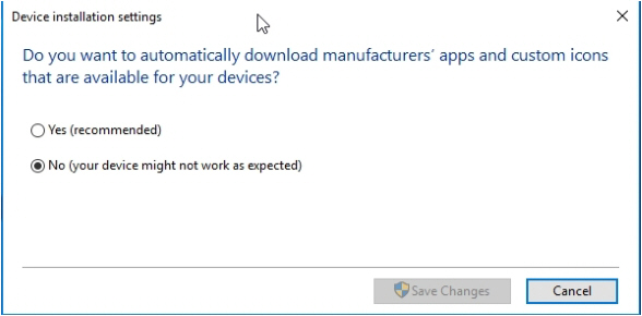
- To the question Do you want Windows to download driver software and realistic icons for your devices?, select No, let me choose what to do and then:
- Select Never install driver software from Windows Update.
- Also deselect the checkbox in front of Automatically get the device app and info provided by your device manufacturer.

- Click Save Changes.
Select correct power options
Aim
To make sure the computer shuts down properly.
Background information
On computers with Windows 10, by default the computer resumes rather than restarts after shutdown. This can cause problems with MediaRecorder and associated software like The Observer XT.
Therefore, we recommend to make sure that the computer really shuts down.
Procedure
- In the Windows start window with apps, type Power options and then click the Power options tile.
- Choose Choose what the power buttons do.

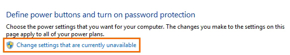
- Click Change settings that are currently unavailable.

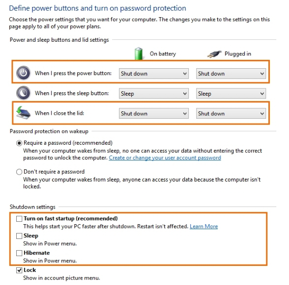
- Select the following options:
When I press the power button – Shut down.
When I close the lid – Shut down.
Under Shutdown settings deselect the checkboxes Sleep, Hibernate, and Turn on fast startup (recommended).
Install MediaRecorder and device drivers
Aim
To install MediaRecorder and, for some recording devices, their drivers.
Procedure
IMPORTANT - If you have an older version of MediaRecorder - Uninstall MediaRecorder 6.0 and older versions before you install MediaRecorder 6.5.
- Download the installation files from my.noldus.com, and extract the contents.
- Browse to the file MediaRecorder [Version number] Setup.exe and double-click it.
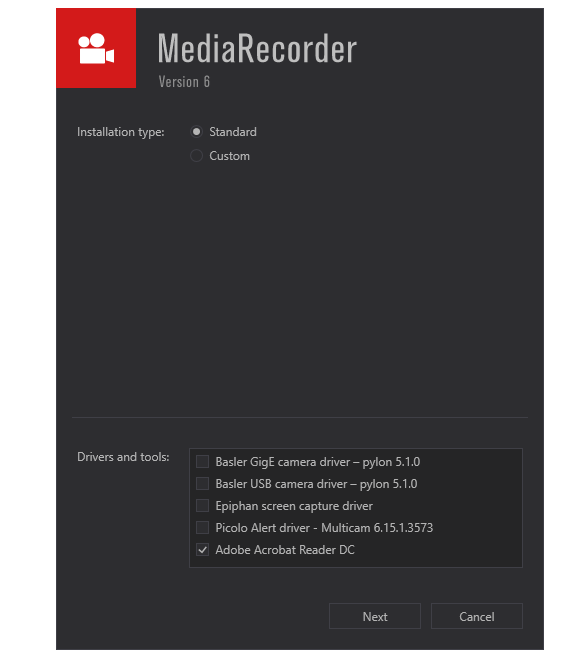
- We recommend to choose Standard as Installation type. Choose Custom only to change the location where the program is installed.

- In the Drivers and tools field, choose the driver of your video device.
- Click Next, accept the License Agreement and click Install.
The following setup prerequisites are installed automatically before MediaRecorder is installed:
- Sentinel Run time — Needed for correct functioning of your hardware key.
- Noldus LeadTools Package 21.
- Noldus MediaLooks Proxy Filters 2.1 — Needed for screen capture of the monitor of the computer with MediaRecorder.
- Medialooks Screen Capture 2.0.3 — Needed for screen capture of the monitor of the computer with MediaRecorder.
- Microsoft .NET Framework 4.7.1 —To run MediaRecorder. This program is installed only when not already present on the computer.
Activate your MediaRecorder license
A license for MediaRecorder comes with an activation key. The key determines which license options are available to you (see Modules in Welcome to MediaRecorder). For existing customers it is still possible to upgrade their hardware key and use this key as the license.
To activate your MediaRecorder license with your activation key:
- Start the MediaRecorder software and select the option Activate software license key.
- Select either Floating or Fixed and click OK.

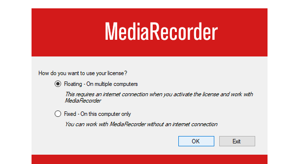
What is the difference between a Floating and a Fixed activation?
When you have a software license key you can choose between a Floating and a Fixed activation.
- Floating activation — Choose this option if you want to be flexible on which computer you use MediaRecorder. If you bought, for instance, a software key with two licenses, you can simultaneously use the software on, for instance, the MediaRecorder computer in lab 1 and 2. If your colleague wants to use MediaRecorder as well (in lab 3) then this is possible. You can install and activate MediaRecorder on as many computers as you want but with two licenses you can use the software only on two PCs at a time. If you want to use MediaRecorder on a third PC, the software should not be running on one of the other two PCs. Please note that a computer must have an internet connection to activate and work with a Floating license.
- Fixed activation — A Fixed activation is linked to one computer. The advantage of having a Fixed activation is that you do not need an internet connection to work with the software. If you bought a software key with, for instance, two licenses, you can activate MediaRecorder on two computers (if you choose ‘Fixed’ for both licenses). If you want to use MediaRecorder on a third computer, you have to deactivate one of the licenses and activate it on the new computer. See Deactivate your MediaRecorder license for more information. Please note that a computer must have an internet connection to activate/deactivate a Fixed license. After you have activated the license you can use MediaRecorder without internet. Alternatively, you can activate/deactivate your license using your smartphone.
Activate your floating license
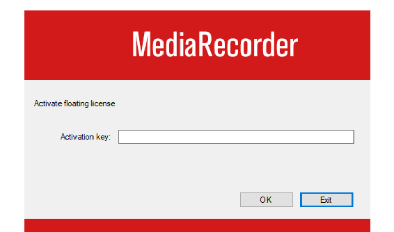
Enter your Activation key and click OK. The MediaRecorder software now opens.
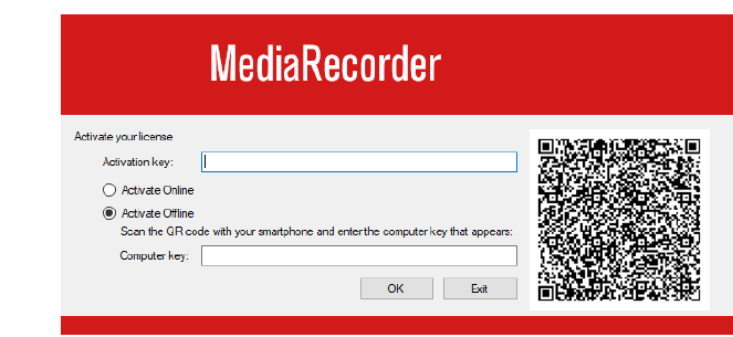
Activate your fixed license
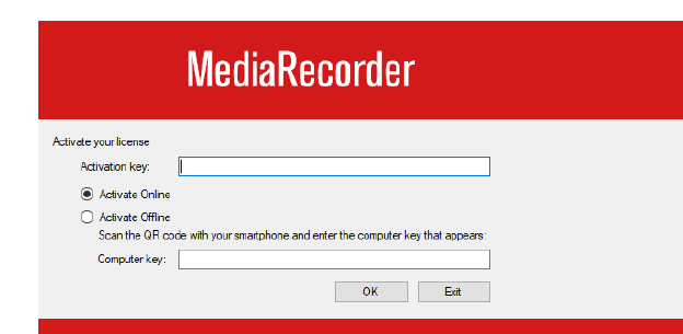
Enter the Activation key that you received with the software and select
- Activate Online if the PC is connected to the internet. When you click OK the MediaRecorder software opens.
- Activate Offline if the PC does not have an internet connection. Scan the QR code with your smartphone, click WEB, enter the Computer key and click OK. The MediaRecorder software opens. .
Deactivate your MediaRecorder license
Deactivate your fixed license if you reached your maximum number of activations and you want to install and use MediaRecorder on another computer.
IMPORTANT If you want to uninstall MediaRecorder, first deactivate the license otherwise you will lose it. Please contact Noldus Technical Support if this happened.
Deactivate your floating license
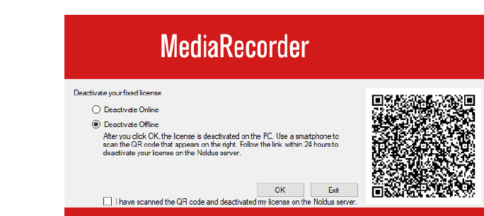
Deactivate your fixed license
- Deactivate Online if the computer is connected to the internet. You will get a message that your license key was successfully removed and that MediaRecorder will exit. Click OK to close the software.
- Deactivate Offline if the computer does not have an internet connection. Scan the QR code with your smartphone. Click OK to deactivate the license on the PC. You will get a message that your license key was successfully removed and that MediaRecorder will exit. Click OK to close the software. Follow the QR code link on your smartphone within 24 hours to deactivate your license on the Noldus server. You can also first deactivate your license on the Noldus server and then select the checkbox in the window on your PC to deactivate the license on your PC.
If you have a hardware key
MediaRecorder is not sold any more with a hardware key; instead, it comes with a software activation code which makes it easier to work with the software. If you use a version earlier than 6.2, it is possible to upgrade your hardware key (see Upgrade your MediaRecorder license to continue working with your hardware key) or request a software activation key. If you wish to use an upgraded harware key, follow the steps below:
- Plug the key into a USB port on your computer. If the hardware key is correctly connected, a red light is visible inside the key.
- Now start MediaRecorder. Keep the key inserted in your computer while you work with MediaRecorder.
A hardware key is a very important piece of equipment, as it represents the full value of your license and cannot be replaced if lost. You can install MediaRecorder on any computer as long as it meets the System Requirements. However, to work with the program you need to insert the hardware key into one of the computer’s USB ports.
IMPORTANT Please make sure that you do not lose the key! You will need to pay for a new license if so. Also be careful with it, because it is sensitive and can be easily damaged.
The drivers for the hardware key are installed together MediaRecorder. It is important to install MediaRecorder with the drivers for the hardware key before you connect the license key to the computer. If you connect the hardware key first, drivers are automatically installed which may lead to incorrect functioning of the hardware key. When the hardware key is installed and connected properly, a red light glows inside it.
End-User Licence Agreement
Revised: 21 July 2022
END-USER LICENSE AGREEMENT
IMPORTANT – READ CAREFULLY. Please read this EndUser License Agreement ("EULA" or “Agreement”) carefully before checking the “accept” checkbox, downloading or using the Software (as defined below). By checking the “accept” checkbox, downloading, installing or otherwise using the Software, End-User agrees to be bound by the terms and conditions of this EULA. If you do not agree to the terms and conditions of this EULA, do not check the “accept” checkbox and do not download, install or use the Software.
The Software is protected by copyright laws and international copyright treaties, as well as other intellectual property laws and treaties. The Software is licensed, not sold.
.
1. DEFINITIONS
Terms used in this EULA but not otherwise defined shall have the meaning assigned to them below:
1.2. End-User: the individual or legal entity that has acquired or uses the Software under the terms and conditions of this EULA.
1.3. EULA: this End-User License Agreement.
1.4. Indirect Losses: any indirect loss, claim, damage, liability, or expenses (including reasonable attorney's fees), including lost profits, and damage due to the stagnation of business operations.
1.5. Network License: a licensing mechanism comprising a license file and accompanying software managing the number of concurrent users of the Software.
1.6. Noldus: Noldus Information Technology BV, with registered office at Nieuwe Kanaal 5, 6709 PA Wageningen, The Netherlands, listed in the Trade Register under Chamber of Commerce number 09094422, or its subsidiaries listed in the document https://www.noldus.com/legal/noldus_corporate.pdf.
1.7. Security System: a system of software protection to limit installation and use of the Software to the authorized End-Users and computers.
1.8. Security Device: a device that forms part of or is attached to the computer, and is used as part of the Security System to control access to the Software.
1.9. Software: the software (including, but not limited to, any updates, upgrades and associated media, printed or electronic documentation and online services) provided to the End-User by Noldus or an Authorized Partner together with this EULA, that is not covered by third party terms and conditions and is included in the list under “Noldus software” in the Annex to the General Terms and Conditions (https://www.noldus.com/legal/noldus_gtc.pdf).
2. LICENSE
2.1. Upon payment by the End-User of the license fees for the Software, Noldus grants End-User a revocable, non-exclusive license to download, install and use the Software in accordance with the terms and conditions of this EULA. This EULA does not grant any rights to obtaining future upgrades, updates or supplements of the Software. If upgrades, updates or supplements of the Software are obtained, however, the use of such upgrades or updates is governed by this EULA and the amendments that may accompany them and may be subject to additional payments and conditions.
2.2. The End-User may download, install and use the Software on as many computers as is reasonably necessary, however the Software may not be shared or used concurrently on more computers than for which EULA’s are granted. End-User shall take all reasonably required steps to ensure that this number is not exceeded.
2.3. End-User is allowed to store or install a copy of the Software for back-up or archival purposes.
2.4. End-User shall not (i) modify, alter, adapt, merge, decompile or reverse-engineer the Software or any part thereof nor create any derivative works based on all or any part of the Software, or (ii) remove or obscure any copyright, trademark or other ownership notices from the Software, or (iii) sub-license, sell, rent, lease, hire, loan, assign or otherwise transfer the Software or your rights in the Software or any part thereof, except as provided for in this EULA.
2.5. The Software may be protected by a Security System, including but not limited to the use of expiry dates, time-limited or feature-limited licenses, authorization codes, Security Devices and Network Licensing. End-User is prohibited to (attempt to) remove, alter or circumvent in any way any part of such Security System.
2.6. End-User is responsible for regular, frequent and effective backups of all files produced or modified while working with the Software.
3. INTELLECTUAL PROPERTY
3.1. All title, copyright and other industrial, intellectual or proprietary rights in and to the Software (including but not limited to any images, photographs, animations, video, audio, music, and text incorporated into the Software), the accompanying printed materials, and any copies of the Software are owned by Noldus or its Authorized Partners. All rights not expressly granted are reserved by Noldus.
3.2. The Software may include or make use of third party software, including open source software. Such third party software may be subject to the third party’s terms and conditions provided in the documentation accompanying the Software and may contain copyright or other industrial, intellectual or proprietary rights of such third party. End-User hereby agrees to the terms and conditions for such third party software. In the absence of any third party terms and conditions, this EULA will govern the third party software in the Software.
3.3. End-User may, from time to time, provide Noldus with comments, suggestions, data, information or feedback (“Feedback”) on the Software. End-User acknowledges and agrees that such Feedback may be freely used by Noldus, at its sole discretion, for the design, development, improvement, marketing and commercialization of its products and services, without any restrictions based on confidentiality or intellectual property rights.
4. TRANSFER
4.1. End-User is entitled to make a one-time, permanent transfer of this EULA and Software only directly to one other End-User. This transfer must include all of the Software (including all component parts, the media and printed materials, any upgrades and this EULA). Such transfer may not be by way of consignment or any other indirect transfer and shall be subject to the following provisions:
a. End-User will provide to Noldus prior to any such transfer the full name and address details of the new End-User and the expected date of transfer in writing;
b. The new End-User understands and agrees to all the terms and conditions of this EULA in the same way as if the new End-User had obtained the Software from Noldus or an Authorized Partner;
c. End-User will destroy all (partial) copies of the Software and all accompanying materials, including but not limited to installed copies and any backup copies on data storage devices and guarantee to Noldus in writing that this has been done. If the Software is an upgrade, any transfer must include all prior versions of the Software;
d. Noldus reserves the right to levy an administrative charge upon the End-User and/or the new End-User in relation to transfer of the Software to an End-User.
4.2. Any attempted transfer without prior written permission from Noldus shall constitute a material breach of this Agreement and shall be deemed null and void.
5. TERM; TERMINATION
5.1. The EULA shall enter into force on the date of acceptance by the End-User and continue until terminated in accordance with this Section 5.
5.2. If the Software is licensed on a subscription basis, the EULA shall continue until the end of the current subscription period.
5.3. Noldus is entitled to terminate the EULA immediately upon prior written notice upon:
a. the breach of any material provision of this Agreement by the End-User if (i) such breach is not curable or (ii) if curable, the End-User has not cured such breach within 30 (thirty) day period following receipt of a written notice by Noldus substantiating such breach ("ingebrekestelling");
b. the filing or institution of bankruptcy, liquidation or receivership proceedings of the End-User or in the event a receiver or custodian is appointed for the End-User’s business, or if its business is discontinued or if it has a petition presented by a creditor for its winding up or if the End-User enters into any liquidation (other than for purpose of reconstruction or amalgamation.
5.4. Upon termination of the EULA, the End-User shall immediately discontinue the use of the Software and remove the software of all computers, destroy all (partial) copies of the Software from all storage media and return the documentation and materials relating to the Software to Noldus or its Authorized Partner.
5.5. Termination of this Agreement does not remove or reduce End-User’s obligation to pay any outstanding license fees or other monies, all of which shall be due for payment immediately on termination of the EULA.
5.6. The following provisions shall survive termination of this EULA: Sections 3, 7, 9, 10 and this Section 5.6. In addition, any other provisions which are required to interpret and enforce the Parties' rights and obligations under the EULA shall also survive any termination or expiration of this EULA, but only to the extent required for the full observation and performance of the EULA.
6. WARRANTY
6.1. Noldus warrants that the Software as of the date of delivery to the End-User by Noldus or its Authorized Partner, the Software will, for a period of 90 days (“Warranty Period”) materially conform to the specifications set out in the user documentation accompanying the Software (“Specifications”), provided that:
a. the Software is properly installed on a supported computer platform (as defined in documents that can be accessed on https://my.noldus.com) and used in accordance with the provisions of the accompanying user documentation and/or any Noldus-approved training course;
b. Noldus is notified in writing within 14 days after any non-conformity of the Software was known or should reasonably have been known to End-User and the End-User has made available all the information that might reasonably be required to allow Noldus to investigate, recreate and where possible remedy a non-conformity;
c. the Software has not been (a) altered, repaired or modified by any party other than Noldus or a third party provider approved by Noldus; or (b) used with software or a computer platform other than set out in the documents that can be accessed on https://my.noldus.com or have been subjected to negligence, or computer or electrical malfunction; or (c) were used, adjusted, or installed other than in accordance with instructions by Noldus.
6.2.Other than set out in Section 6.1, no warranties are expressed or implied with respect Software or any element thereof, including without limitation its quality, performance, accuracy, merchantability or suitability or fitness for any purpose, whether or not that purpose has been communicated by End-User to Noldus. The Software is a general product developed by Noldus for a wide range of solutions, requirements and situations and End-User is responsible for purchasing
the Software required for his needs. Noldus explicitly does not warrant that the Software shall be entirely without error or fault nor that it will operate without interruption. End-User agrees that such errors, faults or interruptions shall not be deemed material and cause to terminate this EULA.
6.3. The warranty by Noldus set out in Section 6.1 applies only to the first installation of the Software and will not apply, resume or renew upon delivery or installation of any subsequent update or upgrade to the Software, alteration in the number of EULA’s granted for use of the Software, or any other extensions, upgrades or alterations to the Software where the Software has previously been delivered to or installed by the End-User.
6.4. The warranty by Noldus set out in Section 6.1 shall further not apply to Software that is licensed or otherwise made available at no cost, or Software that is designated as ‘prototype’, ‘alpha’ or ‘beta’ code, all of which are provided ‘as is’ and without warranty, representation or liability.
6.5. Upon receipt of an End-User’s written notice of the Software not conforming to the Specifications during the Warranty Period, Noldus shall at its option and in its sole discretion (i) assist the Customer in correcting or replacing the non-conforming Software or, (ii) terminate the EULA immediately and refund the purchase price paid by the End-User. The remedies described above shall be End-User’s sole and exclusive remedies. Upon expiration of the Warranty Period, Noldus shall have no obligation to provide such remedies.
6.6. Noldus and Authorized Partners, are not responsible for maintaining or supporting use of the Software or obligated to provide any updates, fixes or support to the Software unless otherwise expressly agreed in writing between End-User and Noldus or the Authorized Partners.
7. USE LIMITATION; LIABILITY; INDEMNIFICATION
7.1. End-User acknowledges that the Software is intended for research or training purposes only and agrees not to use the Software for diagnosis or treatment of disease in human subjects. End-User agrees not to use the Software in any application where the failure, malfunction or inaccuracy of the Software carries the risk of death or bodily injury.
7.2. Noldus Software shall not be used for collection of biometric data from human subjects without prior informed consent from the person whose data is being captured.
7.3. Noldus does not allow the use of its Software for the following applications:
a. Active defense, i.e. embedding Noldus Software in a weapon system;
b.Biometric data collection in criminal, security-related or similar investigations or procedures
c. Surveillance of people in public spaces for security purposes.
d. Any other use that may potentially violate fundamental human rights (https://www.un.org/en/about-us/universal-declaration-of-human-rights)
7.4. If Noldus notices that its Software is used for applications that it does not approve, this may lead to discontinuation of customer support and termination of the EULA.
7.5. To the fullest extent permitted by law, and not withstanding any other provision of this EULA to the contrary:
- a. In no event will Noldus or the Authorized Partners be liable to the End-User for Indirect Losses or for special, incidental, consequential, exemplary, enhanced, or punitive damages, including without limitation, any damages resulting from interruption of business, loss of use, loss of profits or revenue, or loss of business, arising out of or in connection with this EULA, the Software, or the performance of Noldus, the Authorized Partners, or third parties engaged by Noldus in the performance of this EULA, regardless of whether Noldus, the Authorized Partners, End-User, or any other person or entity has been advised of (or could have reasonably foreseen) the possibility of such damages or Indirect Losses. If, despite the provisions in this EULA, liability exists anyway, only direct damage will be eligible for reimbursement.
7.6. Noldus’ and Authorized Partners’ liability shall also be excluded, and Noldus and the Authorized Partners shall not have any liability under this EULA in the event of:
- a. End-User’s use of the Software other than in accordance with Section 7.1;
- b. in the event of direct and indirect consequences of the End-User’s failing to adhere strictly to the user documentation provided or made available by Noldus or the Authorized Partner; or
- c. any loss of or damage to files or data howsoever caused.
7.7. A liability claim will be unenforceable and lapse unless Noldus or the Authorized Partner receives a written notice thereof no later than 6 months after the discovery of an event or circumstance that gives or may give rise to that claim.
7.8. Noldus will hold harmless, defend, and indemnify End‐User from and against all losses, damages, claims, liabilities, and expenses incurred by End‐User that arise out of, relate to, or are caused by any third party claim that End‐User’s use of the Software, pursuant to the terms of the this EULA, infringes the intellectual property rights of such third party. If such a claim is made or appears likely to be made, Noldus, at its option, will have the right to either (i) procure for the End‐User the right to continue to use the Software, (ii) modify or replace the Software so that it is no longer infringing (in a manner that substantially retains its functionality and quality), or (iii) require End‐User to terminate the use of and return the Software and refund a pro rata portion, if any, of the amount paid by End‐User to Noldus for the infringing Software. Notwithstanding the foregoing, Noldus will have no liability to End‐User if the infringement results from use of the Software in combination with software not provided by Noldus or from modifications made by Noldus to conform to specifications provided by End‐User. The indemnification obligations in this section are subject to: (i) End‐User giving Noldus prompt written notice of any claim (provided that End‐User's failure to provide prompt written notice will only relieve Noldus of its obligations under this Section to the extent such failure materially limits or prejudices Noldus’ ability to defend or settle such claim); (ii) the transfer of sole control of the defense and any related settlement negotiations to Noldus; and (iii) End‐User's cooperation, at Noldus’ expense, in the defense of such claim. THIS SECTION STATES END‐USER'S SOLE AND EXCLUSIVE REMEDIES FOR THIRD PARTY INTELLECTUAL PROPERTY INFRINGEMENT CLAIMS.
7.9. End-User shall indemnify and hold harmless Noldus, the Authorized Partners, and the third parties engaged by Noldus from and against any and all losses (including Indirect Losses and special, incidental, consequential, exemplary, enhanced, or punitive damages) arising out of or caused by (i) any failure in the performance of the obligations of the End-User under the law, this EULA, or Noldus’ General Terms and Conditions, or (ii) any and all third party claims on any grounds whatsoever, directly or indirectly related to the End-User’s use of the Software, the contents thereof, or any results or materials generated by the Software.
7.10. THE LIMITATION OF LIABILITY PROVISIONS SET FORTH IN THIS SECTION 7 SHALL APPLY EVEN IF END-USER’S REMEDIES UNDER THIS EULA FAIL OF THEIR ESSENTIAL PURPOSE.
7.11. Noldus and End-User acknowledge and agree that the parties entered into this EULA in reliance upon the limitations of liability set forth in this Section 7, that the same reflect an allocation of risk between the parties (including the risk that a contract remedy may fail of its essential purpose and cause consequential loss), and that the same form an essential basis of the bargain between the parties.
8.MISCELLANEOUS
8.1. Parties may communicate with each other by electronic mail. Parties recognize the risks associated with electronic mail and declare that they shall not hold each other liable for any damage incurred by either of them as a result of the use of electronic mail. If a Party is in doubt as to the content of an electronic message received, the content of the message originating with the sender shall be decisive.
8.2. The invalidity or unenforceability of any provision this EULA shall not affect or limit the validity or enforceability of any other provisions thereof. Any such invalid or unenforceable provision shall be deemed to be substituted by a provision that is considered to be valid and enforceable. The interpretation of the substituting provision shall be as close as possible to the economic, legal and commercial objectives of the severed provision.
8.3. Failure by Noldus or the Authorized Partner to enforce any of its rights under the EULA shall not constitute a waiver of such rights thereunder and shall not relieve End-User of its obligation to comply with such provisions. No waiver or amendment of any provisions therein shall be effective unless signed in writing by a Noldus representative. Any such written waiver shall only be applicable to the specific instance to which it relates and shall not be deemed to be a continuing or future waiver
8.4. Amendments or changes to this EULA can only be agreed upon in writing between the Parties.
8.5. The EULA shall be binding upon the Parties thereto, their legal representatives, successors and assigns. End-User shall not assign any right or obligation arising out of this EULA without the prior written consent of Noldus. Any attempt by End-User to assign or delegate any obligation hereunder shall be deemed null and void.
9.GOVERNING LAW: END-USERS USA OR CANADA
9.1. If End-User is a legal entity and its principal place of business is located in the United States of America or Canada, or if End-User is an individual whose primary residence is located in the United States of America or Canada:
a. This EULA is exclusively governed by the laws of the Commonwealth of Virginia and the applicable federal laws of the United States of America, without regard to the conflicts of law provisions of any jurisdiction. Without limiting the previous sentence, End-User and Noldus expressly agree: (i) that the Virginia Uniform Computer Information Transactions Act, Virginia Code §§ 59.1-501.1 et seq. (“UCITA”), and the United Nations Convention on Contracts for the International Sale of Goods (“CISG”) are expressly excluded from this EULA, (ii) that any and all terms contained in UCITA or CISG will have no force or effect on any portion of this EULA, and (iii) that UCITA and CISG do not apply to this EULA or the Software.
b. Any and all claims and disputes arising out of or in connection with this EULA, the Software, or the performance or non-performance by either party of any of its obligations under this EULA, which End-User and Noldus cannot resolve amicably within a reasonable period of time, will be commenced and maintained only in a state or federal court of competent subject matter jurisdiction situated or located in the United States of America. Noldus and End-User consent to the exclusive personal jurisdiction of and venue in any such court.
c. To the extent permitted by law: End-User must commence or file any claim or action arising out of or relating to this EULA or the Software within six months after the cause of action accrues, otherwise, such claim or cause of action is permanently barred. To the extent permitted by law, End-User expressly waives the right to commence or file any such claim or action under any longer statute of limitations.
10.GOVERNING LAW: END-USERS OTHER COUNTRIES
10.1. If End-User is a legal entity and its principal place of business is located in any country other than the United States of America or Canada, or if End-User is an individual whose primary residence is located in any country other than the United States of America or Canada:
a. This EULA is exclusively governed by the laws of The Netherlands. The United National Convention for Contracts on the International Sale of Goods is expressly excluded.
b. Any disputes arising out or in connection with this EULA that cannot be solved amicably within a reasonable period of time will be submitted to the competent court in Arnhem, The Netherlands, for any dispute with End-Users having their principal place of business in the European Union. In the event that an End-User has its principal place of business outside the European Union, the United States of America or Canada, any dispute shall be finally settled in accordance with the Arbitration Rules of the Netherlands Arbitration Institute. Location shall be Arnhem, The Netherlands. The arbitration procedure shall be conducted by one (1) arbiter in the English language.
Acknowledgments and copyright notices
MediaRecorder is a product of Noldus bv. However, MediaRecorder would not be what it is without the use of third-party software. This page lists software libraries and other software products used in MediaRecorder and links to license and compliance information and/or acknowledgments thereof.
For the complete Terms and Conditions in PDF format, see the PDF files in the folder Documentation\Legal\Acknowledgments, located in your application folder (default: C:\Program Files\Noldus\MediaRecorder 6).
|
Name |
Description |
Link/ License |
|
Adobe Acrobat Reader DC
|
Software for viewing PDF files |
Adobe Distribution Agreement |
|
Apache Thrift |
Combines a software stack with a code generation engine to build services that work efficiently and seamlessly between C++, Java, Python, PHP, Ruby, Erlang, Perl, Haskell, C#, Cocoa, JavaScript, Node.js, Smalltalk, OCaml and Delphi and other languages. |
Apache Software Foundation Apache License 2.0 |
|
Boost |
Open source (Boost community) software library, C++ templates |
Boost software license |
|
Ephiphan driver |
A driver for Epiphan screen capture devices. |
Epiphan Software License Agreement |
|
Euresys H264 Picolo
|
Driver for the Euresys Picolo video capture cards
|
Euresys Terms & conditions |
|
HASP |
Library for software protection
|
Safenet EULA https://safenet.gemalto.com/DownloadNotice.aspx?dID=8589947119 Sentinel Gemalto |
|
LEADTOOLS DirectShow filters |
Video encoder and decoder software |
LEADTOOLS |
|
Live555 |
A set of C++ libraries for multimedia streaming |
Live network Inc. License agreement http://www.live555.com/liveMedia/faq.html#copyright-and-license |
|
MediaLooks DirectShow filters |
Video mixer and screen capture software |
MediaLooks End User License Agreement |
|
Pylon Camera Software Suite Windows |
A driver for Basler cameras |
End-User License Agreement |
|
Windows API Code pack - Core |
Core library for Windows API Code Pack |
Microsoft Software License Terms Microsoft Windows Api Code Pack For Microsoft .net Framework https://github.com/aybe/Windows-API-Code-Pack-1.1/blob/master/LICENCE |
|
Windows API Code pack - Shell |
Shell library for Windows API Code Pack |
Microsoft Software License Terms Microsoft Windows Api Code Pack For Microsoft .net Framework https://github.com/aybe/Windows-API-Code-Pack-1.1/blob/master/LICENCE |
|
Wix Toolset
|
Tools for software installers
|
Wix Toolset http://wixtoolset.org/ .NET Foundation Microsoft Reciprocal License (MS-RL) |
Upgrade to MediaRecorder 6.5
Procedure
- Upgrade MediaRecorder
- Upgrade your MediaRecorder license to continue working with your hardware key
- Upgrade recording devices
Upgrade MediaRecorder
Aim
To upgrade an older version of the MediaRecorder software to version 6.5.
Prerequisites
You have an older MediaRecorder version.
You obtained an activation key for your MediaRecorder license.
Procedure
- Download the installation files from my.noldus.com, and extract the contents.
- Browse to the file MediaRecorder [Version number] Setup.exe and double-click it.
- Follow the steps on your screen to install MediaRecorder 6.5.
- Activate your MediaRecorder license.
Upgrade your MediaRecorder license to continue working with your hardware key
Aim
To configure your hardware key so that you can use it with the upgraded version of MediaRecorder.
Prerequisites
- You upgraded MediaRecorder, or bought additional modules.
- You obtained an upgrade key for your MediaRecorder license.
Procedure
- Insert the hardware key into your computer and start the new version of MediaRecorder.
- The system automatically detects the old license on the hardware key and the Enter Upgrade Key window appears. Enter the key codes that were supplied to you by Noldus IT. These numbers are normally sent by e-mail or are present in your welcome letter.

Notes
- MediaRecorder 6.5 can be installed parallel to MediaRecorder 5, however, we recommend to uninstall older versions.
- If you have a previous version of MediaRecorder on a computer with an operating system other than the 64-bit versions of Windows 10, you should either upgrade Windows, or install MediaRecorder on a computer with one of these operating systems.
- After upgrading to MediaRecorder 6.5, new settings should be made for the cameras.
Upgrade recording devices
Drivers and firmware
A device driver is software that allows communication between your operating system and the recording device. Noldus IT tests MediaRecorder with the latest device drivers and does not support older drivers. When you upgrade MediaRecorder, usually you must also upgrade device drivers.
Firmware is software that is present in the recording device. Not all recording devices have firmware. Noldus tests MediaRecorder with the latest firmware and does not support older firmware, unless stated otherwise. When you upgrade MediaRecorder, you may also need to upgrade device firmware.
Upgrade device drivers
- Uninstall the old drivers with Windows Programs and Features. To do so, open the Control Panel and select Programs and Features. Locate the driver of your recording device and click Uninstall.
See the section your recording device for details on the driver names. - Install the new camera drivers.
See the section on your recording device how to do so.
Upgrade firmware
Check the website of the manufacturer of the recording device whether new firmware is available. If this is the case, install the new firmware.
Recording Devices
Recording devices
Supported device types
MediaRecorder is supported with the following device types. See the section on the device type which specific devices have been tested.
Analog cameras
When do I need an analog camera?
Under certain conditions analog cameras will serve you better than digital cameras. If cables longer than 5 m are needed between the camera and recording equipment, for most digital cameras, you need an amplifier. Industrial analog cameras may be more suitable in these cases. Cable lengths of 30-50 meters are generally no problem.
An additional advantage of analog cameras is that their signals can easily be splitted by simply splitting the cable. To split a signal from a digital camera a video splitter or video splitting software is needed.
Install and setup
To convert the output of analog cameras into a digital format, a video capture card is needed. If you bought a complete solution from Noldus IT, the video capture card is present in the computer. If you bought your cameras, video capture card and MediaRecorder separately, you must do the installation and setup yourself.
Supported analog cameras
In theory, MediaRecorder works with output of every analog camera that is used with the Euresys Picolo Alert PCIe Video Capture Board. We specifically tested MediaRecorder with output of the following cameras with the Euresys Picolo Alert PCIe Video Capture Board with Multicam driver 6.15.13573:
- Ikegami B/W ICD-49 PAL
- Panasonic WV-CP504 NTSC
- Ikegami Analog PAL/CCIR
- Ikegami Analog NTSC/EIA
Maximum supported number of cameras
- Euresys Picolo Alert PCIe Video Capture Board - Four cameras or PhenoTyper Top Units.
Tested setups with EthoVision XT
The table below shows the maximum supported (1) resolution, (2) frame rate (fps), (3) color space, (4) number of devices and (5) recording time (hours). Tests were done on a Dell 3640 PC
|
|
Device |
Resolution |
Frame rate |
Color space |
No of devices |
Recording time |
|
|
Ikegami B/W ICD-49 PAL- Analog CCIR Euresys Picolo Alert PCIe |
768 x 576 |
25 |
YUY2 RGB32 |
1 |
0.5 |
|
|
Panasonic WV-CP504 NTSC - Analog EIA Euresys Picolo Alert PCIe |
640 x 480 |
30 |
YUY2 |
1 |
0.5 18 60 |
|
|
Analog PAL/CCIR |
768 x 576 |
25 |
RGB24 |
4 |
24 |
|
|
Analog NTSC/EIA |
640 x 480 |
30 |
RGB24 |
4 |
24 |


IMPORTANT The file size of a 18, 24 and 60 hours recording is very large.
Note CCIR is the monochrome version of PAL and EIA is the monochrome version of NTSC.
Cable length
In theory, a length of 250 m should be possible, however we did not test that. We know that a length of 100 m can be used without problems.
Notes
PAL or NTSC
MediaRecorder automatically identifies the analog cameras as PAL / CCIR (=monochrome PAL), or NTSC / EIA (=monochrome NTSC). It selects the correct frame rate and resolution automatically.
IP cameras
When do I need an IP camera?
IP cameras are connected directly to a network. IP cameras are especially useful to film for example at a remote location and receive the video files through an Ethernet network on your computer.
Network requirements
To use MediaRecorder with IP cameras, the following network requirements apply:
- An Intel Pro/1000 CT or Intel Pro/1000 PT (1 Gb) network adapter is installed in the computer with MediaRecorder.
- The cables are suitable for Gigabit Ethernet. The minimum cable quality is CAT5e.
See https://en.wikipedia.org/wiki/Category_5_cable
- We recommend to use a dedicated network.
Install and setup
If you bought a complete solution from Noldus IT, the network adapter is present in the computer, the IP cameras are set up and the MediaRecorder settings are made. If you bought your cameras and MediaRecorder separately, you must do the installation and setup yourself.
Supported IP cameras
- Axis M5525
- Axis M1075
- Axis M1375
Cable length
In theory, for IP devices, a cable length 150 m should be possible. However, it has not been tested by us. We know that a setup with a cable of 1 m and an extension cable of 50 m with a switch between the cables works well with MediaRecorder.
Notes
ONVIF Profile S
ONVIF is a communication standard for network devices. ONVIF Profile S applies video and audio streaming and PTZ control. Most IP cameras nowadays support ONVIF Profile S. For cameras that do so, pan, tilt, and zoom control can be done with MediaRecorder and audio from the camera can be recorded. For cameras that do not support ONVIF, pan, tilt, and zoom control must be done with a browser and audio must be recorded with a microphone connected to the sound card of the computer.
Power over Ethernet
IP cameras can be connected to a PoE (Power over Ethernet) or PoE+ switch to supply them with power. This way no extra power cables are needed. Each device is connected to one channel on the switch. A PoE switch can deliver up to 15 Watt per channel. A PoE+ switch has a higher capacity per channel (up to 30 Watt per channel). Make sure that the maximum total capacity of the switch is high enough for all cameras together.
Cameras may also be powered using a 2 or 4-port Network Interface Card (NIC).
Example - you connect four cameras that need 30 Watt each to a POE+ switch. This POE+ switch must deliver at least 4 x 30 = 120 Watt.
- Axis M5525 - requires a regular PoE switch.
- Axis M5054 - requires a regular PoE Switch.
- Axis P1375 - requires a regular PoE switch.
The PoE or PoE+ switch must allow a speed of at least 1 Gb per second.
USB devices
What information are you looking for?
Important notes about USB
USB 2 and 3 ports
The supported USB devices are all USB 3 devices and need to be connected to a USB 3 port. You recognize USB 3 ports by a double-S in front of the USB icon. Some USB 3 ports and connectors have blue labeling.


The Dell Precision T3640 desktop PC sold by Noldus IT has both USB 2 and USB 3 ports. The Dell Precision 3551 mobile workstation only has USB 3 ports.
USB hub
Do not connect your cameras to a USB hub. If you run short of USB connections, connect your license key, keyboard or mouse to a USB hub and connect your USB device directly to the USB port on your computer.
Cable length
USB devices can be connected to the computer without an amplifier with a cable of 5 m. For every subsequent 5 m, an amplifier must be used each. In theory, when using a standard resolution, the cables could be extended this way to 30 m. However we know that not all devices support this.
When do I need a USB camera?
USB cameras are very easy to use. However, the settings may be limited, fo rexample, many USB cameras have fixed zoom. A USB camera may be perfectly suitable for a usability study in which you film a person sitting behind a computer. A USB camera also works very well to create video files for FaceReader. On the other hand, when you need to create a video file of a person further away from your camera, a USB camera may be less suitable.
For videos with accurate time information, needed for EthoVision XT, you need a high-quality USB camera.
Supported USB cameras
- Basler acA1920-155um
- Basler acA2040-90uc
Other USB cameras may also work. However, it could be t.hat you have to change the Color space to MJPG. See Show frame rate, resolution and format
Tested setups with EthoVision XT
The table below shows the maximum supported (1) resolution, (2) frame rate (fps), (3) number of devices and (4) recording time (hours) and (5) whether the test has been carried out on a desktop PC (Dell T3640) or a laptop (Dell 3551)
|
|
Device |
Resolution |
Frame rate |
No of devices |
Recording time |
Desktop or laptop |
 |
Basler acA1920-155um |
1920 x 1200 1920 x 1080 |
60 |
1 |
0.5 |
D |
 |
Basler acA2040-90uc |
2040 x 2046 |
5 10 25 50 |
1 |
8 |
D |
|
|
Basler acA2040-90uc* |
2040 x 2046 |
25 |
1 |
1 |
D |
|
|
Basler acA2040-90uc** |
2040 x 2046 |
25 |
1 |
48 |
D |
|
|
Basler acA2040-90uc |
1920 x 1200 |
60 |
1 |
10 |
L |
* Tested with output quality settings “EthoVision” and “DanioVision”.
** Tested with output quality setting “EthoVision”.
Tested setups for use in The Observer XT - portable set-up
The table below shows the maximum supported (1) resolution, (2) frame rate (fps), (3) number of devices and (4) recording time (hours). Tests were done on a Dell 3551 notebook
|
|
Device |
Resolution |
Frame rate |
No of devices |
Recording time |
 |
Logitech Brio (separate videos, Picture-by-picture & Picture-in_picture, camera audio only) |
1920 x 1080 |
30 |
2 |
1 |
|
|
Logitech Brio |
4096 x 2160 |
10 |
1 |
0.5 |
Notes
- When using the Logitech Brio camera, you have to change the Color space to MJPG. See Show frame rate, resolution and format.
- With multiple USB 3 cameras it takes a while before they become visible in MediaRecorder as it takes time for USB 3 cameras to initialize.
- Encoding the video stream of USB 3 cameras requires quite some processing capacity, which increases power consumption. If you use the supported devices on our recommended laptop, be aware that after 1 hour recording the battery level drops from fully charged to 45%.
GigE Vision cameras
GigE Vision cameras are hereinafter referred to as GigE cameras.
When do I need a GigE camera?
GigE cameras are high-performance industrial cameras. They can have a higher frame rate and resolution than the other supported cameras. The images are sent unprocessed to the computer using a standard network cable (UTP). With a high frame rate and resolution this results in a very high transfer of data. You can connect a GigE camera directly to an Ethernet card on your computer. In this way you can obtain very high quality videos. An important advantage of GigE cameras is the possibility to have long cables between the camera and the computer.
Network requirements
To use MediaRecorder with GigE cameras, the following network requirements apply:
- An Intel Pro/1000 CT or Intel Pro/1000 PT (1 Gb) network adapter needs to be installed in the computer.
https://en.wikipedia.org/wiki/Category_5_cable
- The cables must be suitable for Gigabit Ethernet. The minimum cable quality is CAT5e.
- We recommend to use a dedicated network.
Install and setup
If you bought a complete solution from Noldus IT, the network adapter is present in the computer, the GigE cameras are set up and the MediaRecorder settings are made. If you bought your cameras and MediaRecorder separately, you must do the installation and setup yourself.
Power over Ethernet
GigE cameras can be connected to a PoE injector. This is a device that passes power along with data (in this case, video data from the camera) on twisted-pair Ethernet cabling. Cameras may also be powered using a 2 or 4-port Network Interface Card (NIC). This way no separate power supply is needed.
Supported GigE camera
- Basler GigE camera acA1300-60gm mono. Color space: Y800.
- Basler GigE camera acA1920-40gc color. Color space: RGB32.
Tested setups with EthoVision XT
The table below shows the maximum supported (1) resolution, (2) frame rate (fps), (3) number of devices and (4) recording time (hours). Tests were done on a Dell T3640 PC
|
|
Device |
Resolution |
Frame rate (fps) |
No of devices |
Recording time (hrs) |
|
|
Basler acA1300-60gm |
640 x 480 800 x 600 1024 x 768 1280 x 1024 |
60 |
1 |
0.5 |
|
|
Basler acA1300-60gm |
1284 x 1025 |
25 60 |
1 |
8 |
|
|
Basler acA1300-60gm |
960 x 640 |
30 60 |
4
|
24 |
|
|
Basler acA1300-60gm |
1280 x 1040 |
40 |
4 |
24 |
|
|
Basler acA1300-60gm* |
1280 x 960 |
60 |
4 |
1 |
|
|
Basler acA1920-40gc |
1920 x 1200 |
25 |
1 |
18 |


* Tested with output quality setting “EthoVision” and “DanioVision”.
IMPORTANT The file size of a 8, 18 and 24 hours recording is very large (at least 12 GB).
When four devices were tested, separate videos were made.
Cable length
In theory, a cable length of 150m is possible. However, the maximum length tested in-house with satisfactory results was 25 m.
Screen capture devices
When do I need a screen capture device?
You can easily record what your test participant is doing on his or her computer with a screen capture device. Such a device will provide you with high quality images of the screen at which the test participant is looking.
Supported screen capture devices
Epiphan screen capture devices
Epiphan screen capture devices are hardware devices that will stream the screen captures of the test computer to the computer with MediaRecorder. MediaRecorder supports Epiphan Pearl Nano.
See Epiphan screen capture devices
MR Screen Capture tool
The Screen Capture tool is an add-in to your MediaRecorder license.
See: Use of the Screen Capture tool
Use of the Screen Capture tool
Using the standard Screen Capture tool in MediaRecorder
The Screen Capture tool is an add-in to your MediaRecorder license. It allows you to record the screen of the computer with MediaRecorder. It is a software tool that is built in in MediaRecorder.
IMPORTANT To record the screen of a computer other than the one with MediaRecorder installed, use an Epiphan screen capture device instead.
Prerequisites
- You record the full screen of the PC with MediaRecorder.
- You record one screen only.
- You use MediaRecorder on the Dell Precision 3551 mobile workstation.
See also System requirements.
Drivers
For the MR screen capture option, you do not need to install device drivers.
Supported setup (portable lab)
The table below shows the maximum supported (1) resolution, (2) frame rate (fps), and (3) recording time (hours) on a 3551 notebook.
|
|
Device |
Resolution |
Frame rate |
Recording time |
|
|
Logitech Brio + Built-in screen capture |
1920 x 1080 |
30 |
1 |


Other USB cameras may also work. However, it could be that you have to change the Color space to MJPG. See Show frame rate, resolution and format.
You can also combine built-in screen capture with, for instance, an IP camera.
Procedure
- In MediaRecorder, choose File > Video Settings.
- From the Video device list, select Medialooks Screen Capture.

- Click the Advanced Video Settings button to select recording options.

- In the Medialooks Screen Capture Properties window that opens, select the frame rate and resolution in the Output field. Although you are allowed to select a high frame rate, the actual frame rate of the recording will depend on the processor speed of your computer. Most likely this will be in the order of magnitude of 10 frames per second.

- Although this window has several recording options, the use of the built-in screen capture is designed and supported to record one window on the MediaRecorder computer only. Minimize MediaRecorder after you start recording.
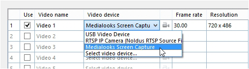
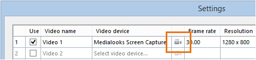
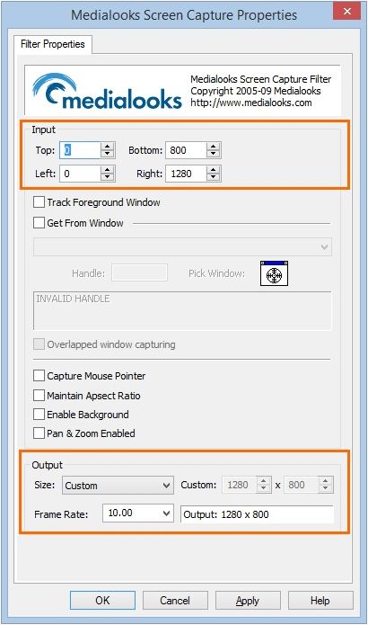
To re-enable settings
As soon as you select the screen capture device, it is used for the video preview and you cannot change its settings. The Output fields are grayed out. To enable these fields again:
- Close the Medialooks Screen Capture Properties window.
- From the Video device list choose Select video device and click Apply.
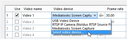
Reselect the Medialooks Screen Capture device again and click the video icon to re-open the Medialooks Screen Capture Properties window (see step 3 above). You can now change the frame rate and resolution again.
Note
The actual resolution of the recorded file may be lower than the value set in Output.
The use of built-in screen capture option is supported with a Windows text size of 100% or 125% (Control Panel > Display).
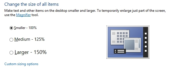
If you change Windows text size to 125%, this may result in MediaRecorder capturing only part of the screen. To solve this, do the following:
- Make sure MediaRecorder is not running.
- Open the folder C:\Program Files\Noldus\MediaRecorder 6.
- Right-click the file MediaRecorder.exe and select Properties.
- Open the Compatibility tab.
- Select Disable display scaling on high DPI settings and click Apply.

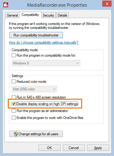
Epiphan screen capture devices
Supported devices
MediaRecorder supports Epiphan Pearl Nano. This is an encoder device that is able to stream the output of the video card of the test computer to the computer with MediaRecorder.
Notes
Audio
To record audio, connect a microphone to the sound card of your computer and select that source in MediaRecorder settings.
Input
Epiphan Pearl Nano only uses HDMI input.
Frame rate
The actual frame rate of the recorded video is limited by the bandwidth of the screen capture device.
Resolution
To record enough screen detail, we recommend to use signal resolution as frame size when using the screen capture device. MediaRecorder supports a resolution of 1920 x 1200. However, screen capture devices by default use the resolution of the screen of the test computer. To change the recorded resolution, change the resolution of the monitor of the test computer.
Recording video
Record video
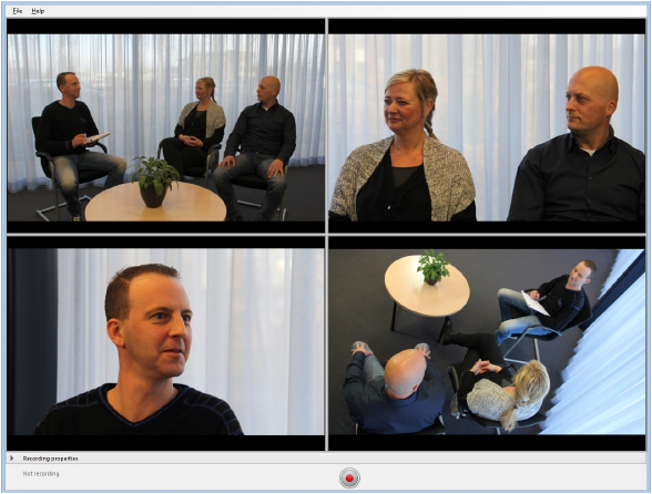
Main topics
- To get started
- Select a video device
- Select an audio device
- Video file options
- Record your videos
- Options
- Save the camera settings
- Use commands to control video recording with other software.
- Picture by Picture resolution
To get started
Main steps
To start working with MediaRecorder involves the following steps:
- Connect all devices and, if applicable, switch them on.
- If you have a hardware key - Insert it into a USB port of the computer.

- Start MediaRecorder. The main window now opens. The first time it opens, the preview window is black. That is because you still have to select the cameras. Proceed with the next steps to do so.
- Click Video Settings to select the cameras, microphones and, optionally, the output. See:
Select a video device
Select an audio device
Video file options
- Record your videos

Select a video device
Aim
To select the cameras for recording.
Prerequisites
- Your devices are connected to the computer with MediaRecorder, and, if applicable, switched on.
- MediaRecorder is open.
- You opened the Video Settings window. To do so, choose File > Video Settings, or click Video Settings in the main window.

tip If the Video Settings button is not visible, the recording properties may be closed. Click Recording Properties at the bottom of your window. By default the recording properties are open.
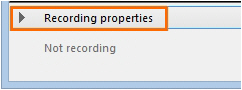
Procedure
In the Video Settings window:
- Select your camera from the Video device list.

IMPORTANT
If you have IP cameras see Set up IP cameras how to set these up and select them in MediaRecorder.
If you use the Screen Capture tool, see Use of the Screen Capture tool on how to select the built-in screen capture device. - Select the preferred frame rate and resolution. The options depend on your type of camera.

- For advanced camera settings, click the video symbol next to the name of your camera. The available options depend on your camera. For some cameras you can zoom and adjust settings for brightness and contrast.

- Optionally change the names in the Video name column, to, for example, Webcam, or IP camera.
- To record audio as well, continue with Select an audio device
- Optionally adjust Video file options
- When satisfied with the settings click OK to return to the main window and record your videos (see Record your videos)
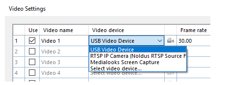
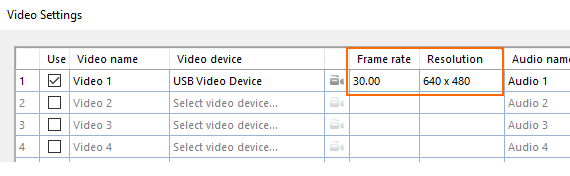
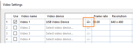
Note
Frame rate and resolution
By default, the optimal combination of frame rate and resolution for the camera is selected. If you increase the frame rate, the maximum resolution available goes down and vice versa. If you select an impossible combination of frame rate and resolution and format, MediaRecorder gives a warning (see below).
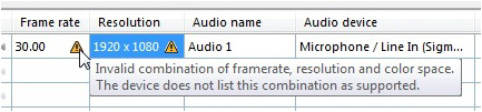
Select an audio device
Aim
To select the audio source.
Prerequisites
- Your devices are connected to the computer with MediaRecorder, and, if applicable, switched on.
- MediaRecorder is open.
- You opened the Video Settings window. To do so, choose File > Video Settings, or click Video Settings in the main window.
Procedure
- In the Video Settings window, select the microphones under Audio device. Choose between your computer microphone, a separate microphone, or the audio stream of your camera. Choose No audio if you do not wish to record audio.
- Optionally record the same audio stream in all videos. To do so, select this checkbox. It means that the device defined as Audio device 1 will supply the audio stream for all your videos.

Check that the green bar is maximal when speech level is normal.
Please note that in Picture-in-Picture mode, you may select which audio source to use for all the videos. This may be important if the first video is the screencapture device, which does not record audio. To do so, select this checkbox:
 (For the Picture-in Picture mode, see the Output settings in Video file options).
 - Click the microphone button for Audio settings.

The available options depend on your microphones. Move the sliders to adjust the recording volume.
To check the recording volume, right-click the speaker icon in the bottom-right corner of your window and select Recording devices.

- Optionally, change the names in the Audio name column.
- Optionally, adjust the Video file options
- When satisfied with the settings click OK to return to the main window and Record your videos
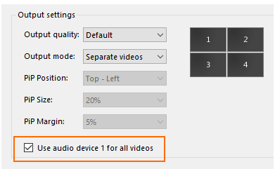
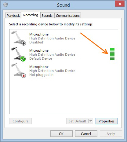
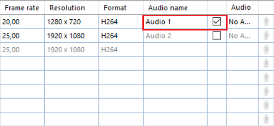
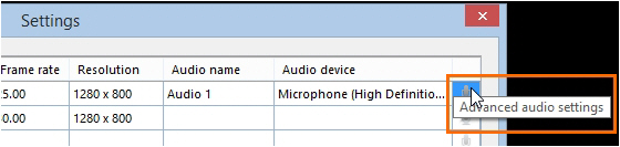
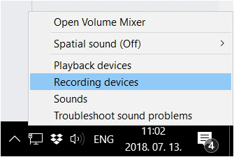
Note
Audio is needed and has been tested only for cameras that are supported in The Observer XT.
Video file options
Aim
To specify one of the following:
- Format of the recording timer. See Timer format
- Maximum recording time
- Video file output: separate videos, or one video with the images from all the cameras.
See Output settings
Prerequisites
- Your devices are connected to the computer with MediaRecorder, and, if applicable, switched on.
- MediaRecorder is open.
- You opened the Video Settings window. To do so, choose File > Video Settings, or click Video Settings in the main window.
Procedure
Timer format
Select the options from the lists.
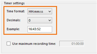
The recording timer is present in the lower-left corner of the main window.
Maximum recording time
Select the checkbox and enter the maximum recording time.
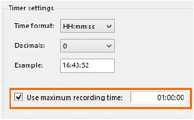
The maximum is 99:99:59 (hr: min: sec). However, see your camera type in the topic Recording devices for the supported maximum recording time.
Output settings
Output Quality - Videos can be recorded in various qualities depending on the use. Videos with a higher compression rate are usually smaller in size, but they take more processing power to create and play, and their quality may be worse compared to those with lower compression rates. If hardware encoding is used to decrease the CPU usage and redirect load to the video card (GPU), it may result in a larger video file.
There are four presets defined, in separate xml files which you can find in C:\ProgramData\Noldus\MediaRecorder\6\EncoderSettings. It is not advised to modify the contents of these files, as they are optimized for the different use cases. For normal use, the default output quality should be used. For EthoVision, DanioVision and the Remote Photo Plethysmography (RPPG) module of FaceReader, special settings are defined.
The special setting for EthoVision is only useful if you record the outputs of four cameras simultaneously. With the default settings, two cameras are recorded on CPU and two on the video card (GPU). This results in differences in file size. By selecting EthoVision as the output quality, all four cameras will be recorded using CPU power.
Output mode - If you have selected more than one video source, the following options are available.
- Separate videos — One video file for each camera.
- Picture by Picture — One video file with the images from each camera next or above each other.

- Picture in Picture — One video file with a large image of the first camera with the images from the other cameras embedded in it.

If you select Picture in Picture the following options become available:
- PiP Position — The position of the embedded images.
- Pip Size — The size of the embedded images. The percentage is based on the width of the first camera image. The aspect ratios of the embedded camera images are maintained.
- Pip Margin — The margin of the embedded images. When the percentage is zero, the embedded images are positioned directly on the edge of the main image. The percentage is based on the width of the first camera image.

Notes
Picture in Picture and Picture by Picture resolution
If possible, choose the same frame rate for all the videos. If you choose different frame rates the videos with the lowest frame rates may flicker and may not be suitable for use in The Observer XT, EthoVision XT, or FaceReader.
Picture by Picture resolution of input videos
The resolution of the resulting video is a sum of the separate videos, with a maximum of 1920 x 1280. If the resulting video exceeds a width of 1920 pixels or a height of 1280 pixels, the video resolution is adjusted proportionally. This requires processor capacity and decreases the quality of the output video. It is better to choose a lower resolution of the individual videos, so that the total resolution does not exceed 1920 x 1280.
See Picture by Picture resolution how the resolution of the resulting video is calculated.
Picture in Picture with portrait format
Please note that if you have multiple videos in portrait format, they may overlap when you use Picture in Picture.
Change the video file location
Aim
To save the videos in another location than the default one.
The default location where MediaRecorder stores its video files is:
D:\Noldus\MediaRecorder\Video Files — If Noldus IT installed your system
C:\Users\Public\Public Documents\Noldus\MediaRecorder\Video Files — In all other cases. It is recommended to set this folder to be located on a separate, fast, large capacity drive.
Prerequisite
You must be able to write in the selected folder and there must be enough file space available (at least 600 Mb per video per hour).
Procedure
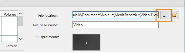
tip Click this button to open the folder with video files in Windows Explorer and play recorded videos.
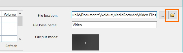
Set video file base name
Aim
To select a word or phrase to start the video file name with.
The video file name consists of the File base name followed by:
- The video input name.
- The date and the time the videos were recorded.
- The number of the video camera.
Example – The File base name is Video, you changed the name of Video 2 to Webcam in the Video Settings window (File > Video Settings), the date is 11 May 2016, the time 10:54:43 and you create 2 videos simultaneously. The name of the second video will then be:
Video Webcam 5_11_2016 10_54_43 AM 2.mp4
Procedure
Enter a name in the File base name field.
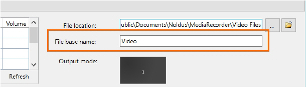
Note
The date and time depend on your computer’s regional settings. To change these, open the Control panel and then Region and Language. Select your preferences in one of the tabs.
Select or deselect videos for recording
Aim
To choose from which video sources to record video files.
Prerequisite
You selected the recording devices in the Video Settings window.
Procedure
Select or deselect video sources for recording in the Use column.
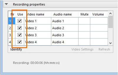
Record your videos
Aim
To create video files from the video stream of the connected recording devices.
Prerequisites
- Your devices are connected to the computer with MediaRecorder, and, if applicable, switched on.
- MediaRecorder is open.
- You selected the cameras and, optionally, microphones and specified the output of the video files in the Video Settings window (File > Video Settings).
Procedure
- When you selected all settings in the Video Settings window, click OK to return to the Main window. You will see a preview of the cameras.

- Optionally, adjust options like the video file location, the video file base name or the order of the video files. See Options
- Press the Start recording button.

- A pop-up window will appear, informing you about Noldus's Data Transparency Policy. Read it carefully before clicking the I will inform the participants button. You can also check the box Don't show me again to prevent further occurrence.

- The button changes into the Stop Recording button and the Recording timer starts running.

- Press the button again to stop recording. Recording stops automatically when you specified a Maximum recording time.
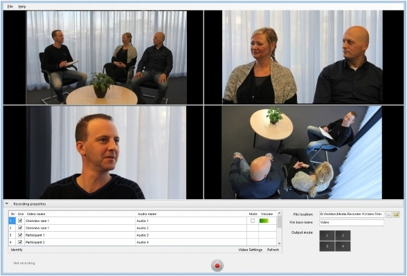
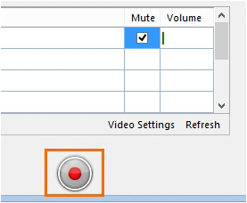
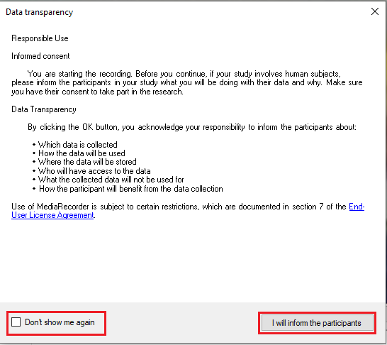
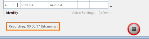
Note
If you have IP cameras, see Pan, Tilt, Zoom control with IP cameras how to change the camera view before or during recording.
Mute audio in preview
Aim
To mute audio sources in MediaRecorder. The muted audio is recorded normally in the video files.
Prerequisite
You selected microphones in the Video Settings window.
Procedure
Select the audio sources you wish to mute in the Mute column.
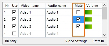
Options
What do you want to do?
- Change the video file location
- Set video file base name
- Select or deselect videos for recording
- Mute audio in preview
- Change video order in preview
- Show frame rate, resolution and format
- Refresh the preview
- See which preview image comes from which camera
- Show or hide recording properties
- Show frame rate, resolution and format
- Enter a default user name and password of IP cameras
- Pan, Tilt, Zoom control with IP cameras
Change video order in preview
Aim
To change the order of the video cameras, for example to change the position of the images in a Picture in Picture recording.
Prerequisite
You selected the recording devices in the Video Settings window.
Procedure
- Drag and drop rows. in the table with video devices or drag and drop the preview images.
- Click the Refresh button.
See Refresh the preview
Note
You cannot drag and drop Picture in Picture, or Picture by Picture preview images. Drag and drop the rows in the table with video devices instead.
Show frame rate, resolution and format
Aim
Procedure
Right-click one of the column headers and select the preferred options.
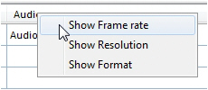
Notes
- The Format column shows the color space of the video file. The column is hidden by default, because the optimal color space is selected by default. See the following page for more information on color space.
http://www.noldus.com/knowledge-base/what-color-space-format-used-media-recorder.
- TIP Follow the same procedure to show or hide the Frame rate, Resolution, and Format columns in the Video Settings window.
Refresh the preview
Aim
To display video images in the preview after a temporary connection loss or if you connected a camera after you opened MediaRecorder.
Procedure
Click the Refresh button.
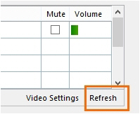
See which preview image comes from which camera
Aim
To see which image comes from which camera.
Prerequisite
You selected the recording devices in the Video Settings window.
Procedure
Press the Identify button.
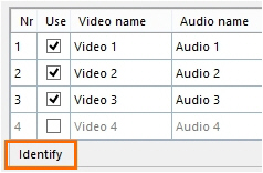
Result — Numbers are superimposed on the camera images. These correspond to the row numbers in the table.
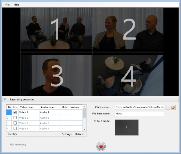
Show or hide recording properties
Aim
To show or hide the table under the preview of the camera images, so that the space for the preview images is increased.
Procedure
Click Recording properties.
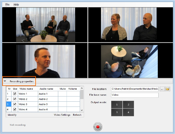
Result
The size of preview images is increased.
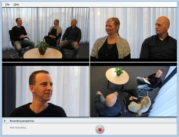
Save the camera settings
Aim
To make a configuration file that can be used to open the correct cameras, microphones and video settings.
Prerequisites
- Your devices are connected to the computer with MediaRecorder, and, if applicable, switched on.
- MediaRecorder is open.
- You selected camera, microphones and video output in the Video Settings window.
See Select a video device, Select an audio device and Video file options for the procedures.
Background
The settings you create for the different cameras are automatically saved when you close MediaRecorder. They are saved to the file Current settings.mrs that is present in the folder C:\Users\Public\Public Documents\Noldus\MediaRecorder. These settings are used when you restart MediaRecorder. But you can also save your own settings, or save different settings for different setups, for example, a webcam for a test participant’s face in a usability test room and three overview IP cameras in an observation room. This way you do not have to select all cameras manually each time.
Procedure
- Choose File > Save Configuration As.
- Give the configuration a name and click Save.
Notes
- To open a saved configuration, choose File > Open configuration.
- IMPORTANT Never shut down the computer by pressing the power button or cutting off the electricity. Your settings may become lost, even after you saved the settings. Always use the Windows shut down feature to close your computer.
- To go back to the default configuration, choose File > Open Configuration. Browse to the file Default Settings.mrs. This file is read-only. When Noldus installed MediaRecorder for you, the file is in the folder D:\Noldus\MediaRecorder. When you installed MediaRecorder yourself, the file is in the folder C:\Users\Public\Public Documents\Noldus\MediaRecorder, or the folder you selected when you installed MediaRecorder.
- If you encounter problems with starting MediaRecorder, for example because you created wrong settings which are loaded when you start MediaRecorder, delete the file Current settings.mrs. MediaRecorder now starts with the default settings and you can create new settings.
Pan, Tilt, Zoom control with IP cameras
Aim
To change the camera view in MediaRecorder.
- Prerequisites
- Your IP camera supports ONVIF Profile S.
- Your IP camera can Pan, Tilt and Zoom.
- The camera is selected in MediaRecorder.
- See Select a video device
Procedure
Hover with your mouse over the camera image. Two buttons appear in the top-right corner of your window.
- Enable or disable PTZ control.

- Open the PTZ preset menu.

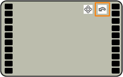
PTZ control
- Click the Enable PTZ button in the image you want to adjust. A four-arrow cross appears in the middle of the image and your mouse pointer becomes a small point.
- Click the camera image and keep your left mouse button pressed to control the camera. The cross now becomes connected to the point and the camera image moves in the direction of the point. The further away from the center cross you click, the faster the camera moves.

- Zoom in and out with your mouse wheel.
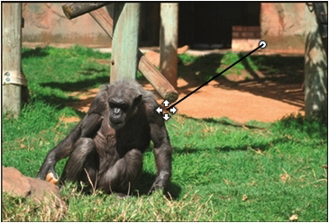
Save camera position
If you are satisfied with the position of your camera, you can save this as a PTZ preset. Hover over the camera image and click the button that opens the PTZ menu.
- Save as first PTZ preset.

- Save as second PTZ preset.

- Return to first PTZ preset.

- Return to second PTZ preset


PTZ keyboard shortcuts
The following keyboard shortcuts can be used to control PTZ:
|
Ctrl + 1 |
Enable / disable PTZ in first video |
|
Ctrl + 2 |
Enable / disable PTZ in second video |
|
Ctrl + 3 |
Enable / disable PTZ in third video |
|
Ctrl + 4 |
Enable / disable PTZ in fourth video |
|
Numerical keypad 1 |
Move camera left-down |
|
Numerical keypad 2 |
Move camera down |
|
Numerical keypad 3 |
Move camera right-down |
|
Numerical keypad 4 |
Move camera left |
|
Numerical keypad 6 |
Move camera right |
|
Numerical keypad 7 |
Move camera left-up |
|
Numerical keypad 8 |
Move camera up |
|
Numerical keypad 9 |
Move camera right-up |
|
Numerical keypad + |
Zoom in |
|
Numerical keypad - |
Zoom out |
Notes
- If you use the CH products RS Desktop joystick for PTZ control, make sure it is connected before you start MediaRecorder.
- To reverse the camera pan or tilt direction, open the Advanced Video Settings window and select the checkbox Flip Pan axis or Flip Tilt axis
See step 11 in Select ONVIF cameras in MediaRecorder in Set up IP cameras
To change the PTZ method
MediaRecorder has two PTZ methods. The default method is described above. it is also possible to let the camera center its camera view to the point that you click with your mouse.

Procedure
- Open MediaRecorder and select your IP cameras.
See Select ONVIF cameras in MediaRecorder - Close MediaRecorder. This saves settings for the IP cameras in the file Current Settings.mrs.
- Create a backup of the file Default Settings.mrs that is present in the folder C:\Users\Public\Public Documents\Noldus\MediaRecorder.
- Open the file Current Settings.mrs from the same folder with Notepad.
- Locate the line <PtzType>1</PtzType> and change 1 to 0. There is a line for each PTZ camera that you selected in MediaRecorder. Change the line for each PTZ camera.
Important When you selected the same camera multiple times in MediaRecorder, use the same method for pan and tilt in each camera. So for each camera, use either 1 or 0. - Save the file as Default Settings.mrs. These settings are used when the file Current Settings.mrs is not found.
- Delete the file Current Settings.mrs from the folder C:\Users\Public\Public Documents\Noldus\MediaRecorder.
- Re-open MediaRecorder. MediaRecorder opens with configuration file Default Settings.mrs and creates a new file Current Settings.mrs with the edited settings. The new PTZ method is now available.
To Pan and Tilt the camera view
- Click the Enable PTZ button in the image you want to adjust.
- A white cross appears. The camera moves to the point that you click with your mouse.
Enter a default user name and password of IP cameras
Aim
To enter the ONVIF user name and ONVIF password of IP cameras only once, in case you have several cameras with the same credentials.
Procedure
- Choose File > Preferences > IP camera settings.
- Select Use default IP camera user name and password.
- Enter the user name and password.

- Follow the procedure in Select ONVIF cameras in MEdiaRecorder or Select devices that do not support ONVIF in MediaRecorder. When you click the Advanced video settings button, the user name and password are filled in automatically.
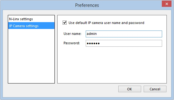
Use commands
Aim
To control video recording with another program that can send commands, for example, EthoVision XT.
- Prerequisites
- Your devices are connected to the computer with MediaRecorder, and, if applicable, switched on.
- You selected cameras, microphones and video output in the Video Settings window of MediaRecorder.
See:
Select a video device
Select an audio device
Video file options
Procedure
In your application, browse to the program MRCmd.exe that is by default located in the folder C:\Program Files\Noldus\MediaRecorder 6 and specify the command.
For example, use the following command line to start video recording:
“C:\Program Files\Noldus\MediaRecorder 6\MRCmd.exe /R”
note If you installed MediaRecorder in another folder than the default one, the program MRCmd.exe is present in this folder. Adjust your command lines accordingly.
Available commands
- Start MediaRecorder – MRCmd.exe or MRCmd.exe /E
- Start recording — MRCmd.exe /R
- Stop recording —MRCmd.exe /S
- Close MediaRecorder — MRCmd.exe /X — Closes MediaRecorder program.
- Load a configuration file — MRCmd.exe /C=[filename.mrs].See Load a configuration file
- Set the file base name — MRCmd.exe /B=[basename]. See Set file base name
There is a space between MRCmd.exe and the slash.
Load a configuration file
The command /C loads a configuration file with the settings for your cameras (Save the camera settings). This is, for example, useful to open MediaRecorder with the correct cameras. Make sure MediaRecorder is not recording at that moment.
By default MRCmd.exe loads a file from the folder C:\Users\Public\Public Documents\Noldus\MediaRecorder. If the file is located in another folder, you must type the full path. If the file name or the path contains spaces you must type it in between quotation marks.
Example 1 - Open MediaRecorder and load Configuration_observation_room.mrs from C:\Users\Public\Public Documents\Noldus\MediaRecorder:
MRCmd.exe /E /C=Configuration_observation_room.mrs
Example 2 - Opening MediaRecorder and load Configuration Control Room from C:\Configuration files:
MRCmd.exe /E /C=”C:\Configuration files\Configuration Control Room.mrs”
Set file base name
The command /B sets the File base name.
Example - Set the File base name to Observation room:
MRCmd.exe /B=”Observation room”
This option cannot be used together with other commands.
Notes
Delay
Allow enough time between the commands. If a command is sent before the previous one is carried out, the second command is not carried out. For example, if the command Start Recording is sent before MediaRecorder is completely open, recording does not start.
There may be a delay between the command Start Recording and the moment the recording actually starts. This delay depends on the number of cameras, camera settings, the processor speed and programs running in the background.
In the most common scenarios with MediaRecorder and The Observer XT, the videos are automatically synchronized with the events, so the delay is not important.
See also Synchronize videos with events in MediaRecorder with The Observer XT
Picture by Picture resolution
The highest allowed resolution of a recorded video is 1920 x 1280. The resolution of a Picture by Picture video is a sum of the separate videos. However, if that exceeds a width of 1920 pixels or a height of 1280 pixels, the video resolution is adjusted proportionally. This requires processor capacity and decreases the quality of the output video. It is better to choose a lower resolution of the individual videos, so that the total resolution does not exceed 1920 x 1280.
The resolution of the picture by picture video is determined in the following way:
- Example 1 — The width of the PbP video is the sum of the width of the separate videos. The height of the PbP video is the maximum height of the separate videos.
- Example 2 — The total resolution is calculated in the same way as in Example 1. The width of the resulting video exceeds the maximum of 1920 pixels. Therefore both the width and height are reduced proportionally, resulting in a width of 1920 pixels.
- Example 3 — The total width is the sum of the width Video 1 and 2. The height of of the resulting video is the maximum height of Video 1 and 2 plus the height of Video 3. Both the width and height of the resulting video will exceed the maximum of 1920 x 1280. Therefore both the width and height are reduced proportionally, resulting in a width of 1920 pixels. The height is now smaller than the maximum of 1280 pixels.
If the height was higher than 1280, the width and height would be reduced further, resulting in a height of 1280 pixels.
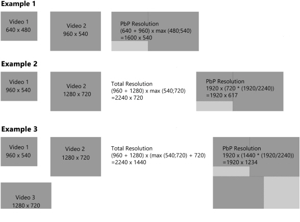
MediaRecorder with The Observer XT
MediaRecorder with The Observer XT

Main topics
- How to record videos for The Observer XT
- MediaRecorder with The Observer XT
- Synchronize videos with events
How to record videos for The Observer XT
You can create videos for use in The Observer XT in two ways. You can either first create videos in MediaRecorder and then make your observations offline using The Observer XT, or you can control the recording process with commands from The Observer XT while making a live observation.
Offline observations using prerecorded video
Making offline observations in The Observer XT means carrying out an observation using a prerecorded video. The video files created by MediaRecorder can be used to observe offline in The Observer XT. No special settings are needed to use files from MediaRecorder in The Observer XT.
Observe live and control MediaRecorder
You can score live in The Observer XT while simultaneously recording a video using MediaRecorder. You can use The Observer XT to control MediaRecorder while making an observation.
This way you can achieve the following:
- When you create an observation in The Observer XT, MediaRecorder opens and the correct configuration file is loaded.
- When you start an observation in The Observer XT, video recording with MediaRecorder starts.
- When you stop an observation in The Observer XT, video recording with MediaRecorder stops.
- The recorded videos are automatically linked to the observation in The Observer XT and synchronized with the events.
See MediaRecorder with The Observer XT
MediaRecorder with The Observer XT
Aim
To achieve the following:
- When you create a new Observation, MediaRecorder starts and loads a configuration.
- When you start an Observation, MediaRecorder starts recording.
- When you stop an Observation, MediaRecorder stops recording.
- The recorded videos are automatically linked to the observation and synchronized with the events.
Background
The communication between MediaRecorder and The Observer XT makes use of the Noldus network communication protocol N-Linx.
For details on N-Linx, see the Reference Manual - N-Linx. You find this manual on The Observer XT installation USB stick. You can also download it from the download section of the Noldus website.
Prerequisites
- N-Linx Server is installed on a computer in the network.
- You have The Observer XT 14.1 or higher.
Procedure
Carry out the following steps:
- If MediaRecorder, The Observer XT and N-Linx Server are not all installed on the same computer, make sure that traffic through the N-Linx port is not blocked by Windows Firewall. See Create exceptions for N-Linx port in Windows Firewall
- If MediaRecorder and The Observer XT run on different computers, make sure that The Observer XT can access the MediaRecorder videos. See Make sure The Observer XT can access the MediaRecorder video files
- Install N-Linx Agent on the computer with MediaRecorder. See Install N-Linx Agent
- Create MediaRecorder Settings
- Create The Observer XT settings
- Carry out an observation in The Observer XT
Create exceptions for N-Linx port in Windows Firewall
(2-computer setup)
Aim
To make sure communication between MediaRecorder, The Observer XT and N-Linx Server is not blocked by Windows Firewall. You need to allow inbound and outbound traffic through port 5672 in Windows Firewall on all computers with MediaRecorder, The Observer XT, and N-Linx Server.
Prerequisites
- MediaRecorder, The Observer XT and N-Linx Server do not all run on the same computer. If they do, skip this topic.
- The computers are in the same network.
Procedure
- Open the Control Panel and select Windows Firewall.
- On the left side of the window, click Advanced Settings.
- In the left pane, click Inbound Rules and click New Rule in the Actions pane on the right.
- In the New Inbound Rule Wizard Window that opens, select Port and click Next.
- Select TCP and enter 5672 in the Specific local ports field and click Next.

- Click Allow the connection and click Next.
- Select to which network the rule applies and click Next.
- Give the rule a name, for example N-Linx connection and click Finish.
- Check in the Inbound Rules windows that this rule is set to Enabled.
- In the left pane, click Outbound Rules and click New Rule in the Actions pane on the right.
- Repeat steps 4 to 9 for the outbound rule.
- Close all Control panel windows.
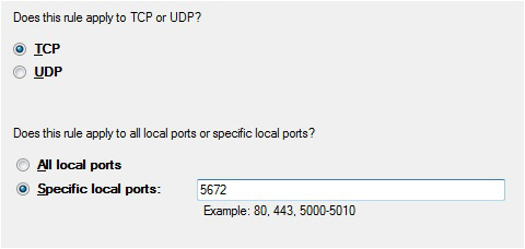
Make sure The Observer XT can access the MediaRecorder video files
(for 2-computer setups)
Aim
To make sure The Observer XT can access the videos recorded by MediaRecorder. The videos are not copied to The Observer XT. The Observer XT creates a link to the MediaRecorder videos.
Procedure
Carry out the following steps:
Share the folder where MediaRecorder stores its video files
- Right-click the folder where the video files are going to be stored, which is by default C:\Users\Public\Documents\Noldus\MediaRecorder\Video Files and select Give access to and then Advanced Sharing Settings.

- Change the sharing options for all your network profiles (‘Private’, ‘Guest or Public’ and ‘Domain’): select the option Turn on file and printer sharing for all your profiles.
- Under ‘All Networks’ select the option Turn on sharing so anyone with network access can read and write files in the Public folders. Then click Save Changes.
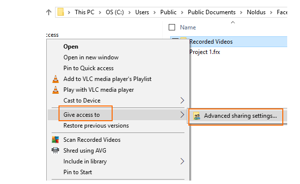
Switch off password protected sharing on the MediaRecorder computer
This procedure is needed to make sure that the folder where MediaRecorder stores its videos files can be accessed without a password by the computer with The Observer XT.
The procedure differs for Windows workgroups and domains. To see whether the MediaRecorder computer is in a workgroup or a domain, open the Control Panel and choose System. The type of network is listed under Computer name, domain, and workgroup settings.
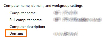
Procedure for workgroup
- Follow the procedure in Share the folder where MediaRecorder stores its video files to open the Advanced sharing settings.
- Under Password protected sharing, select the option Turn off password protected sharing.
Important: If you do not see this option, most likely your computer is in a domain, not a workgroup. Carry out the Procedure for domain below.
Procedure for domain
- Press the Windows key + R.
- Type lusrmgr.msc and press OK.
- Open the Users folder and double-click Guest.
- Deselect Account is disabled and click OK and close the lusrmgr window.
- Press the Windows key + R.
- Type gpedit.msc and press OK.
- Open Computer Configuration\Windows Settings\Security Settings\Local Policies\User Rights Assignment and double-click Deny access to this computer from the network.
- Click Guest and then choose Remove > OK.
- Close the Local Group Policy Editor window.
Map the shared folder with MediaRecorder video files
Carry out this procedure on both computers.
- Open File Explorer and then This PC.
- Click Computer and then click the Map network drive icon.

- Choose a name for the drive and browse to the shared folder.
Important: Make sure you select the same drive on both computers. - Click Finish.
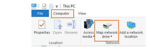
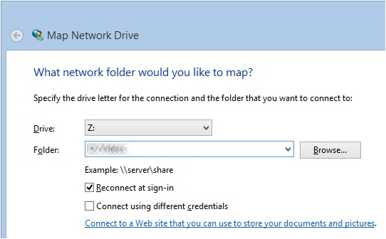
Note
- When you now start the computer with The Observer XT, you need to enter the login details for the computer with MediaRecorder.
Install N-Linx Agent
Aim
To install and set up the tool that starts MediaRecorder when you start an observation in The Observer XT.
important Install N-Linx Agent on the computer with MediaRecorder.
Prerequisite
You installed N-Linx Server on a computer in the network.
Procedure
- From my.noldus.com, download N-Linx Agent Setup.exe.
- In the N-Linx Agent Setup window, select MediaRecorder control in the Drivers and Tools field and click Next.
- Accept the terms in the End-User License Agreement and click Install.
Connect N-Linx Agent to N-Linx Server
- CLick the arrow in the bottom-right corner of your window to open the system tray. Then double-click the N-Linx Agent icon.

- In the N-Linx Server Address field, enter the Computer name of the computer with N-Linx Server. See To find the computer name.
You can also enter the IP address, but then the IP address of the computer with N-Linx Server must be fixed. Ask your system administrator for assistance.
If MediaRecorder runs on the same computer as N-Linx Server, leave the entry localhost in the N-Linx address field. N-Linx Agent then automatically connects with N-Linx Server.
note See To change the port if the default port 5672 is already in use. - If the connection with N-Linx Server is established, the text Connected appears in the lower-left corner of the N-Linx Agent window.
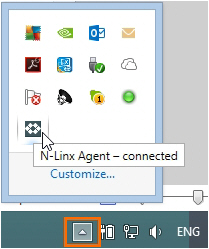
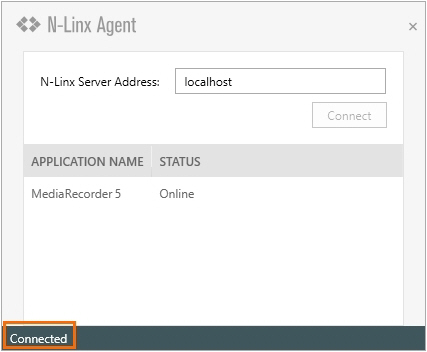
To find the computer name
To find the name of the computer with N-Linx Server, open the Control Panel on that computer and choose System.
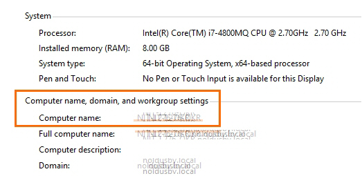
To change the port
N-Linx Agent by default uses port 5672 to communicate with N-Linx Server. If this port is in use, type the new port after a colon in the N-Linx Server Address field. For example:
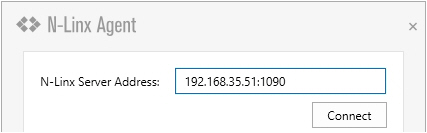
IMPORTANT Select the same port in all components that communicate with N-Linx Server. Also, disable Windows FireWall for this port.
Notes
- N-Linx Agent is installed in the folder C:\Program Files\Noldus\N-Linx Agent 1.
- If you did not install N-Linx Server yet, it will not be possible to establish a connection.
- The Status of MediaRecorder in the N-Linx Agent window is Online when MediaRecorder is open and connected to N-Linx Server.
Create MediaRecorder Settings
Aim
To connect MediaRecorder to N-Linx Server and select the video file folder.
Prerequisites
- If MediaRecorder, The Observer XT, and N-Linx Server are not all installed on the same computer, you created exceptions for the N-Linx port Windows Firewall.
See Create exceptions for N-Linx port in Windows Firewall
- You installed N-Linx Server on a computer in the network.
- N-Linx Agent is installed on the computer with MediaRecorder and connected to N-Linx Server.
See Install N-Linx Agent
Procedure
- In MediaRecorder, choose File > Preferences > N-Linx settings

- Select Allow communication with N-Linx Server.
- In the N-Linx Server address field, leave the default value Localhost if MediaRecorder runs on the same computer as N-Linx Server.
If the programs run on different computers, enter the name of the computer with N-Linx Server. See also To find the computer name - In the N-Linx Server port field, leave the default port 5672. Ask your system administrator for assistance if this port is used by another program.
- When the connection with N-Linx Server is established the Status will be Connected. Click OK.
- If MediaRecorder and The Observer XT run on different computers, select the mapped drive as location to store the video files and not the original folder. The original folder is locally on the computer with MediaRecorder and cannot be accessed by The Observer XT.
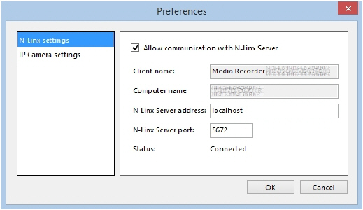
example You mapped the default folder C:\Users\Public Documents\Noldus\MediaRecorder\Video files as X:\. Set the default video file location where MediaRecorder stores its video files to X:\ and not to the original folder.
Create The Observer XT settings
Aim
To enable communication between The Observer XT and N-Linx Server.
Prerequisites
- You installed N-Linx Server on a computer in the network.
- If MediaRecorder and The Observer XT, or N-Linx Server run on different computers, you created exceptions for the port that N-Linx uses in Windows Firewall.
See Create exceptions for N-Linx port in Windows Firewall
- N-Linx Agent is installed on the computer with MediaRecorder and connected to N-Linx Server.
See Install N-Linx Agent
- MediaRecorder is open.
Procedure
- In The Observer XT, choose File > Preferences > N-Linx Settings.
- Select Use N-Linx server to connect with other applications.

- In the N-Linx Server address field, enter the computer name of the computer with N-Linx server. If The Observer XT is installed on the same computer as N-Linx Server, leave the default entry Localhost.
- In the N-Linx Server port field, leave the default port 5672. Ask your system administrator for assistance if this port is used by another program.
- Click Test connection. If connection with N-Linx Server is found, the Status will change to Connected.
- Click OK.
- Choose Setup > Project Setup.
- Under Observation source, select Live Observation. The Devices window now opens. If not, click the Devices button.

- Select MediaRecorder [Version number][Computer name] and click Edit Settings. MediaRecorder now opens if it is not already open.

- Click Edit Settings again. A window with the available configurations (see Save the camera settings in Record video) now opens. Select the configuration file you want to use and click OK. If you do not select a configuration, Current Settings.mrs will be used.
Optionally enter a unique name in the Identify device as field. This way you can control multiple instances of MediaRecorder with one instance of The Observer XT.
-
Repeat the steps 9 and 10 for each MediaRecorder instance.
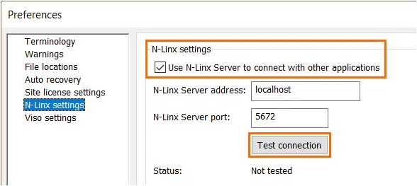
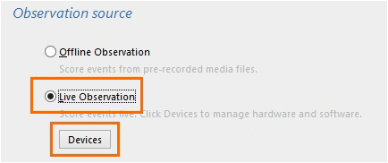
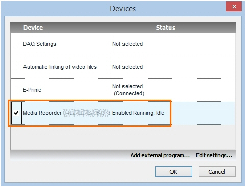
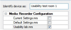
Note
When you close MediaRecorder, the MediaRecorder line in the Devices window (step 9) will be grayed out and the status will change to Disabled. MediaRecorder will start when you create an observation.
Carry out an observation in The Observer XT
Procedure
- In The Observer XT, choose Observe > Observation > New to create an observation.
- See Carry out your observation in The Observer XT Help.
- Press the Start observation button and score the data. See Start the observation and Score data in The Observer XT Help.
- Press the Stop observation button. See Stop the observation in The Observer XT Help.
Note
IMPORTANT Allow enough time between the actions. If you start an observation before MediaRecorder is completely open, video recording will not start.
Troubleshooting
When MediaRecorder control with The Observer XT does not function properly, check the following;
- On the computer with MediaRecorder, check that N-Linx Agent is running. See step 1 in Connect N-Linx Agent to N-Linx Server. If there is no N-Linx agent icon in the system tray, the program is not running. Then double-click the file NLinxAgent.exe in the folder C:\Program Files\Noldus\N-Linx Agent 1.
- On the computer with MediaRecorder, check that the status of the N-Linx Agent is Connected. If not, follow steps 2 and 3 in Connect N-Linx Agent to N-Linx Server.
- In MediaRecorder, check that the checkbox Allow communication with N-Linx Server is selected (see step 2 in Create MediaRecorder Settings).
- In The Observer XT, check that Use N-Linx server to connect with other applications is selected (see step 2 in Create The Observer XT settings) and that the Status in the window is Connected (see step 5 in Create The Observer XT settings).
- In The Observer XT, check that MediaRecorder is selected (see step 9 in Create The Observer XT settings).
- On all computers with MediaRecorder, The Observer XT, and N-Linx Server, check that an exception is made in Windows Firewall for all inbound and outbound traffic through port 5672 (see Create exceptions for N-Linx port in Windows Firewall).
- Check that N-Linx Server is running. To do so, press Ctrl + Shift + Esc and open the Services tab. Locate the line RabbitMQ and check that the Status is Running. If not, right-click the line and select Start.
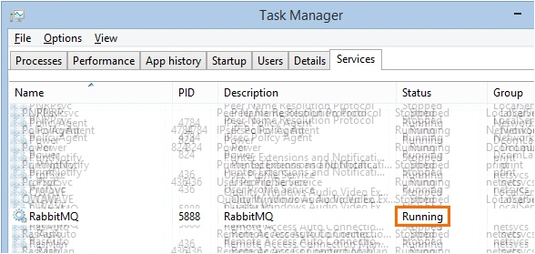
Synchronize videos with events
Aim
To synchronize the MediaRecorder videos with the event log of The Observer XT.
When is manual synchronization not needed?
Videos created by MediaRecorder are automatically synchronized with the events in The Observer XT when you followed the procedure in MediaRecorder with The Observer XT.
An automatic offset is applied to the videos. See View the automatic offset of videos imported into The Observer XT to see which offset was applied.
When is manual synchronization needed?
You need to synchronize videos and events manually in the following situations:
- You start video recording manually and import the videos into The Observer XT.
- You have an older version of The Observer XT that does not support N-Linx data transfer.
- See Synchronize manually for the procedure.
View the automatic offset of videos imported into The Observer XT
Procedure
The procedure depends on what you did:
- You controlled video recording with The Observer XT
- You manually started video recording within 10 seconds after starting the observation in The Observer XT.
You controlled video recording with The Observer XT
Right-click the video in The Observer XT and choose Properties. The field Recording details shows the offset.
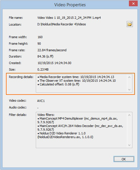
You manually started video recording within 10 seconds after starting the observation in The Observer XT
When you import the videos into The Observer XT, an offset is automatically set. A message with the calculated offset is shown.
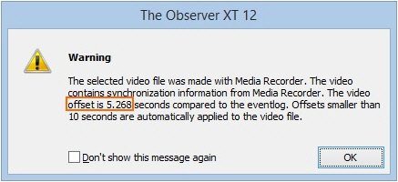
If you right-click the video in The Observer XT, the offset is also shown next to Recording details in the Video Properties window that opens.
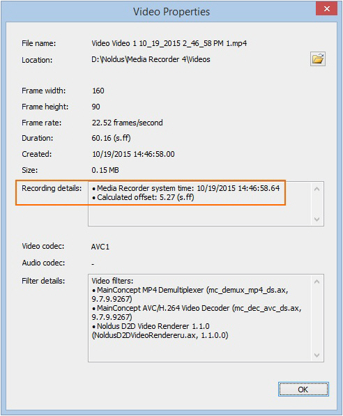
However, there can still be up to 1 second asynchronism between the observation and the video files. If that is a problem for the accuracy of your experiments, Synchronize manually to fine-tune the synchronization.
Synchronize manually
Aim
To synchronize imported MediaRecorder videos with events in The Observer XT
Prerequisites
One of the following situations is true:
- You have The Observer XT 11 or lower
- You have The Observer XT 12.5 or lower and The Observer XT and MediaRecorder run on different computers.
- You manually started video recording more than 10 seconds after starting an observation into The Observer XT. You imported those videos manually into The Observer XT.
Procedure
You must carry out the following steps:
- Determine the time difference between video and events
- Apply offset to correct for the time difference
Determine the time difference between video and events
- Make sure an event is recognizable in the videos and the event log. For example create a dummy behavior with a key code in the coding scheme.
- Carry out an observation and simultaneously record a video or the keyboard.
- In The Observer XT, press the key of the dummy behavior. The event is recorded in the Event log and is visible in the video.
- Import the video into The Observer XT.
- Open the observation and scroll to the recognizable event in the video. Note the time difference of the event in the video and the event log.
Apply offset to correct for the time difference
- 1.In The Observer XT, open the observation and click the Offset button on the toolbar.
- 2.Select Numerical Offset to open the File Synchronization window.

- 3.Set the time difference in the Offset cell. For example, if the video started 0.2 seconds before the observation, enter 0.20 seconds in the Offset field of the video.
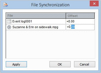
Note
You can also use the SyncBox to assess the delay (see the Technical Note - The SyncBox - The Observer XT for more information).
MediaRecorder with EthoVision XT
MediaRecorder with EthoVision XT
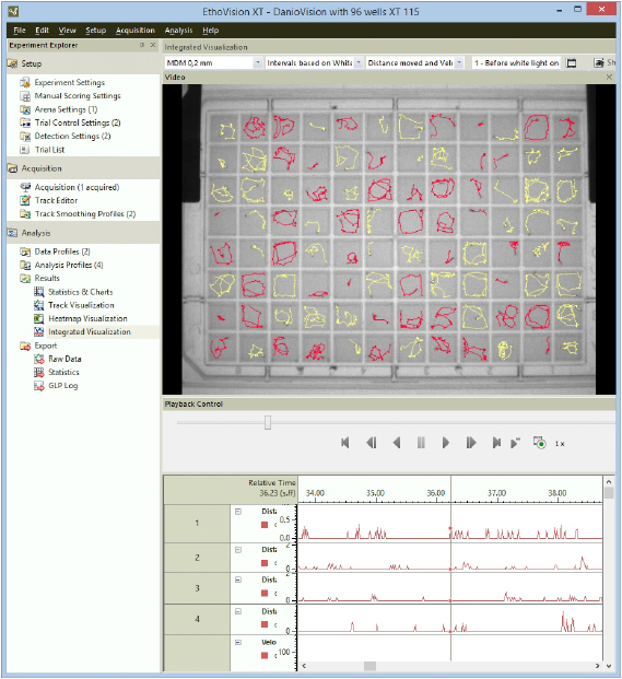
How to record videos for EthoVision XT
You can create videos for use in EthoVision XT in two ways.
- First create videos in MediaRecorder and then track from video file in EthoVision XT
- Control video recording by MediaRecorder with EthoVision XT when you track live
In both cases, if you work with analog cameras, you must adjust the aspect ratio in EthoVision XT. If you work with digital cameras, this is not necessary.
See Adjust the video aspect ratio (analog cameras only)
Prevent black frames at the start of your videos
To make sure that MediaRecorder waits for an I-frame before it starts recording you can edit the VsSettings file that comes with MediaRecorder. If you do not edit this file, your video may start with black frames and EthoVision will not be able to track the video from the start.
The VsSettings file is installed together with MediaRecorder. You can find the file in C:\ProgramData\Noldus\MediaRecorder\6.
By default the ProgramData folder is a hidden folder. In Windows Explorer on the View tab select Hidden items in the Show/hide section to view the folder.
- Right-click VsSettings.xml and select Copy. Right-click and select Paste to make a copy of the file. Keep this copy in case you want to go back to the original settings.
- Open the VsSettings.xml file in Notepad or a similar text editor.
- From the Edit menu select Find and type ‘Wait’ in the search field.

- To make sure that MediaRecorder waits for an I-frame before it starts recording, edit the file and change ‘0’ into ‘1’.

- Save the file.
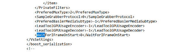

First create videos in MediaRecorder and then track from video file in EthoVision XT
Aim
To create videos that can be used for tracking in EthoVision XT.
Prerequisite
You have cameras that are supported for tracking in EthoVision XT.
Procedure
- Create videos in MediaRecorder.
- In EthoVision XT, select Track from video file and select the video. See the EthoVision XT Help for details.
Notes
- IMPORTANT In theory you can create video files from many different digital cameras with MediaRecorder. However, the quality of the digital camera is essential for accurate tracking. If you use other hardware or cameras than the supported ones, you need to check whether the time information in the video files is correct.
See Test an unsupported setup in Specifications
- When you use analog cameras, you must adjust the aspect ratio. For digital cameras that are not supported this may also be necessary.
See see Adjust the video aspect ratio (analog cameras only)
- Choose EthoVision as the Output Quality if you record from four cameras simultaneously. With the default settings two cameras are recorded on CPU and two on the video card (GPU). This results in differences in file size. By selecting EthoVision as the output quality, all four cameras will be recorded using CPU power. For more information see Output settings.
- Choose DanioVision as the Output Quality if you film DanioVison larvae. With this setting the compression of the video files is limited to have an optimal video quality to detect the small larvae. The file size will be larger than with the default Output Quality setting.
Control video recording by MediaRecorder with EthoVision XT when you track live
Aim
To start video recording automatically when something of interest is detected by EthoVision XT. This is, for example, useful if you have animals that spend a lot of time in a shelter. Start video recording when the animal leaves the shelter.
Prerequisites
- You have cameras that are supported for tracking in EthoVision XT.
- MediaRecorder and EthoVision XT run on the same computer.
Procedure
- In EthoVision XT, open the Trial Control screen by clicking the Trial Control Settings in the Experiment Explorer.
- In the Components pane, under Actions click the button next to External command.

- Enter a name in the Action Name field, for example, Start Recording.

- Under Actions to perform, click the ellipsis button
 and browse to MRCmd.exe. By default MRCmd.exe is present in the folder C:\Program Files\Noldus\MediaRecorder 6\MRCmd.exe.
 - Enter one of the commands that are available for MediaRecorder (/E, /R, /S, /X or no command) as a Command line option.
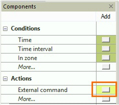
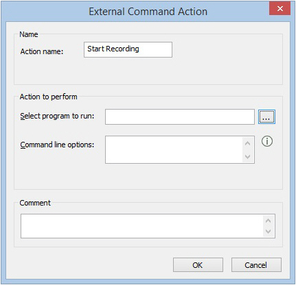

See Use commands in Record video
Example
You carry out live tracking during a 24-hour period and you want to make a recording in MediaRecorder, but only when the animal leaves the shelter.
- Create an external command condition with the command /E to start MediaRecorder.

- Insert a Condition Out of shelter. Combine this condition box with a Time condition, because opening MediaRecorder takes a few seconds. With a Time condition you make sure that MediaRecorder is open before recording starts (see the figure below for an example).
- Insert an External command box with the command /R to start recording.

- Similarly, you can stop recording (Command line option: /S) when the animal enters the shelter again.
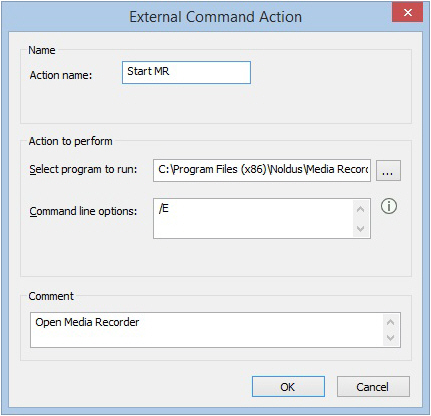
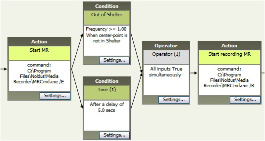
Notes
- For an extensive description of how to use Trial Control, see Trial Control in the EthoVision XT Help or the Reference Manual - Trial and Hardware Control in EthoVision XT.
- IMPORTANT Allow enough time between the actions. If a command is sent before the previous one is carried out, the second command is not carried out. For example, if the command Start Recording is sent before MediaRecorder is completely open, recording does not start.
- There also may be a delay between the issuing the Start Recording command and MediaRecorder actually starting recording. This delay results in missed frames at the beginning of the video file. Run a test recording to see how long this delay is. To assess this delay, make for example a video of a digital clock and check the interval between issuing the Start Recording command and recording the first frame of the video.
Adjust the video aspect ratio (analog cameras only)
Aim
To correct for a distorted video image in EthoVision XT.
Prerequisite
You created videos with MediaRecorder from analog cameras using the Picolo Alert PCIe Video Capture Board.
Procedure
- In EthoVision XT choose Setup > Experiment Settings.
- Choose From Video File as your Video Source. You find more information on how to make Experiment Settings in Set up an Experiment in the EthoVision XT Help.

- Choose Setup > Arena settings, or click the desired Arena Settings in the Experiment Explorer.

- Browse to your video file and grab a background image for your arena. See Arena Settings in the EthoVision XT Help for information on how to do this, and for more information on how to make Arena Settings.
- Click the Adjust Aspect Ratio button.

- In the Adjust Aspect Ratio window choose Noldus Recorder and click the arrow to open the list. Choose:
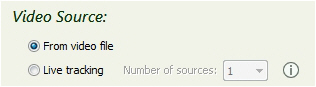
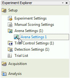
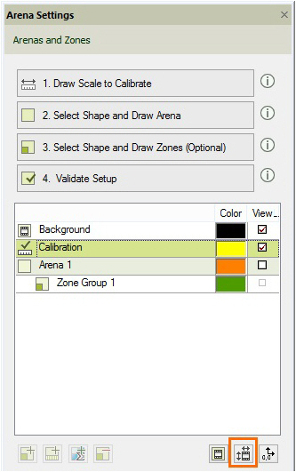
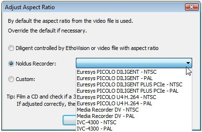
- Euresys PICOLO U4 H.264 – NTSC — For analog NTSC cameras. NTSC cameras are found in North and Central America, together with parts of Asia.
- Euresys PICOLO U4 H.264 – PAL — For analog PAL cameras. PAL cameras are found in Europe and the rest of the world, except for North and Central America, together with parts of Asia.
The other options do not apply for video files created with MediaRecorder.
Notes
- For the supported digital cameras, the default option Diligent controlled by EthoVision or video file with aspect ratio is correct.
- For not supported digital cameras you may need to adjust the aspect ratio. See the section Adjust the video aspect ratio in Arena Settings in the EthoVision XT Help for details.
MediaRecorder with FaceReader
MediaRecorder with FaceReader
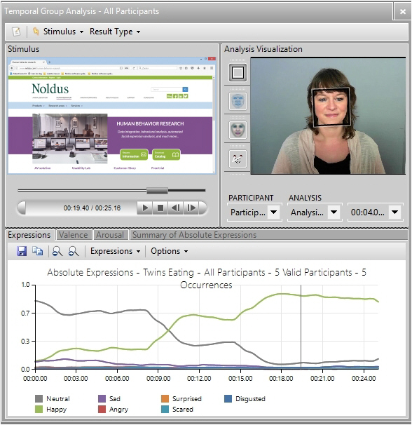
Offline video analysis in FaceReader means analyzing prerecorded videos. The videos created by MediaRecorder can be used for offline video analysis in FaceReader 4 or higher. No special settings are needed to use files from MediaRecorder in FaceReader. However, if you record videos to use with the Remote Photo Plethysmography (RPPG) module in FaceReader we advise to use FaceReader-RPPG as the Output Quality setting. With this setting the videos will only be slightly compressed. The file size of the resulting videos is huge, about 260 Mb/minute. For more information see Output settings.
You cannot simultaneously analyze live video signals in FaceReader and create video files in MediaRecorder. If you want to analyze and record videos simultaneously, record the videos in FaceReader.
Prevent black frames at the start of your videos
To make sure that MediaRecorder waits for an I-frame before it starts recording, you can edit the VsSettings file that comes with MediaRecorder. If you do not edit this file, your videos may start with black frames and FaceReader will not be able to analyze them from the start.
The VsSettings file is installed together with MediaRecorder. You can find the file in C:\ProgramData\Noldus\MediaRecorder\6.
By default the ProgramData folder is a hidden folder. In Windows Explorer on the View tab select Hidden items in the Show/hide section to view the folder.
- Right-click VsSettings.xml and select Copy. Right-click and select Paste to make a copy of the file. Keep this copy in case you want to go back to the original settings.
- Open the VsSettings.xml file in Notepad or a similar text editor.
- From the Edit menu select Find and type ‘Wait’ in the search field.

- To make sure that MediaRecorder waits for an I-frame before it starts recording, edit the file and change ‘0’ into ‘1’.
- Save the file.
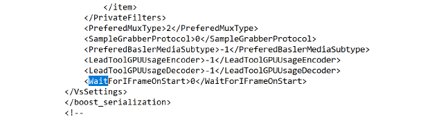
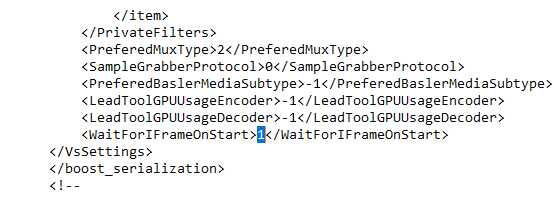
Troubleshooting
Troubleshooting
If you are having problems, please first read Specifications or Requirements of a custom computer, to check whether your system is compatible MediaRecorder. Also check the items below to see if there is a known solution for your problem.
What problem do you have?
- No video preview
- Installation problems
- Sound problems
- Insufficient disc space
- Missing frames when controlling recording with external programs
- Problems loading MediaRecorder
No video preview
If one of your video inputs is black with a warning triangle and the message No signal from Video [n] is shown, the video source was not turned on when MediaRecorder was started. Press the Refresh button in MediaRecorder to show the image from that camera. You also get a black screen with a warning triangle when you have not yet selected this camera in the Video settings window.
See also Save the camera settings in Record video
You will also have a black video input if your computer does not have an Nvidia graphics card. By default, MediaRecorder records two cameras on CPU and two on the video card (GPU) if you record from four cameras simultaneously. Only Nvidia GPUs facilitates the use of the GPU as additional processing power for compression of MediaRecorder videos. Other graphics cards are not able to do that. If you ordered a computer with MediaRecorder from Noldus Information Technology, it has an Nvidia card. By default, MediaRecorder checks whether this card is available and if so, uses it.
If you purchased a PC elsewhere, it may have a different graphics card and with the default settings, your cameras may give black inputs in MediaRecorder. To prevent this, you can edit the VsSettings file that comes with MediaRecorder.
To check the graphics card of your computer, click the Windows button and type ‘Device Manager’. In the Device Manager window expand the Display adaptors section. The computer’s graphics cards are listed here.
The VsSettings file is installed together with MediaRecorder. You can find the file in C:\ProgramData\Noldus\MediaRecorder\6.
By default the ProgramData folder is a hidden folder. In Windows Explorer on the View tab select Hidden items in the Show/hide section to view the folder.
- Right-click VsSettings.xml and select Copy. Right-click and select Paste to make a copy of the file. Keep this copy in case you want to go back to the original settings.
- Open the VsSettings.xml file in Notepad or a similar text editor.
- From the Edit menu select Find and type ‘GPU’ in the search field.

- To make sure that MediaRecorder does not use the GPU, edit the file and change ‘-1’ into ‘0’.
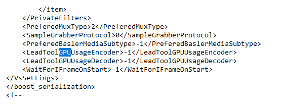
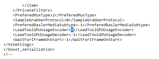
You can also change the value into ‘1’ if your computer has one (Nvidia) graphics card. With this value MediaRecorder will not check what graphics card is available, it will use the card that is installed.
Installation problems
If you get an error message during installation of the Picolo card, it is most likely that the card is not correctly inserted into your computer. Turn the computer off and disconnect the power cable. Press the card gently but firmly into place.
Sound problems
If you are playing back multiple videos in The Observer XT and you hear an echo on the sound track, turn the sound off on all but one of the video monitors.
If you hear no sound on your recording this could be because:
- The speakers of your computer are not plugged in, they are turned off or their volume is low.
- The Windows volume control is muted or turned low.
- You have selected Line-in for your audio device instead of Microphone.
- You do not have an audio source connected.
Insufficient disc space
If your output folder is on the C: drive it is possible that you will have insufficient file space. Most computers are configured with more file space on the D: drive, so select your output folder on the D: drive.
Missing frames when controlling recording with external programs
When you sent commands to the MediaRecorder external programs like EthoVision XT or The Observer XT, there is a small delay in starting the actual recording with The MediaRecorder. This results in some missing frames at the start of the video file. Allow enough time at the start of recording to compensate for this delay. When the command Start Recording is given before MediaRecorder is open and has loaded the cameras, recording does not start.
To measure this delay, make for example a video of a digital clock and compare the time the command “Start Recording” is given with the time at the first frame of the video.
Problems loading MediaRecorder
MediaRecorder opens using the configuration file Current settings.mrs. When problems occur with these settings, open MediaRecorder with the default settings and recreate camera settings. To do so:
- Delete the file Current settings.mrs from the following folder: C:\Users\Public\Documents\Noldus\MediaRecorder
- Re-open MediaRecorder
- Re-select the cameras. A new file Current Settings.mrs is created.
See also Save the camera settings in Record video
Tools for troubleshooting
Videoinspector
This free tool gives basic information about the video files you are trying to play (such as which codecs they were made with) and reports which codecs are installed on your computer. It is reasonably easy to use. It does not report details such as the I-frame rate.
http://www.kcsoftwares.com/?vtb
GSpot
Although GSpot has not been maintained since 2007, it is a powerful tool to get information about both your video file and your computer system. Gspot is a free tool. It is less easy to use than VideoInspector.
In addition to providing detailed information about the video file you have opened, G-Spot can be used to adjust how Windows uses the codecs installed. This is an advanced function and you should only use it if you understand what you are doing, and carefully write down the changes you make. If several codecs are installed which can be used to play one format, Windows assigns a ‘merit’ to each codec to determine its preference. You can use Gspot to change the merit of each codec and in that way select which one is used by Windows (and so by other software). This is a way in which you can solve problems of codecs conflicting with each other, e.g. a piece of software such as The Observer XT works best with a particular codec, but another installation has set the merit of an alternative codec higher.
Mediainfo
MediaInfo provides detailed information about media files. It has less information than GSpot, but at the publication date of this manual, it was maintained.
http:/www.mediainfo.sourceforge.net/en
Windows System Information
This can be obtained in Windows with System and Security/System/Advanced System Settings, Dxdiag.exe, and the Device Manager (in the Control Panel).
For full system information, SIW is a useful tool.
Support
Help menu
MediaRecorder’s Help menu contains the following options:
- Help topics – Opens the MediaRecorder Help. You can search and find help topics.
- Noldus Online – If your computer is connected to the Internet, you can choose this option to go to the MediaRecorder home page on the Noldus website or to the MyNoldus portal. On the MyNoldus portal you can download the latest version of the software and documentation, submit support cases and view your account information. If you encounter a problem with MediaRecorder, you can inform Noldus IT with the Report an Issue option.
- Upgrade – If you have purchased an upgrade of MediaRecorder, choose this option to type the new Upgrade Key number that you have received from Noldus.
- About MediaRecorder– Choose this option to see details of exactly which version of MediaRecorder you are using. Click User Info to see the registered user and license number of your software.
Technical support
For questions about MediaRecorder or any other Noldus product, contact the Support department by opening the Help menu in MediaRecorder, select Noldus Online and subsequently Get Support. The help desk may ask for the file MediaRecorder log file. You can find this file in the folder C:\Users\<login name>\AppData\Local\Temp.
Record at a predefined time
Record at a predefined time
Aim
To schedule video recording. This is especially useful when you want to start recording in the middle of the night, or you do not want to disturb the test subjects by handling the video software.
IMPORTANT The procedure below is an example of the possibilities of Windows Task Scheduler, which is a default program in Windows 10. Since Windows Task Scheduler is a Microsoft program, Noldus IT offers no support for this feature.
Procedure
- Type Task Scheduler in the Apps window.
- Choose Action > Create Task.
- In the General tab, type a name in the Name field, for example MediaRecorder with Webcam.
- Optionally enter other settings in this tab and open the tab Triggers.
- Click the button New.
- Select On a schedule from the list next to Begin the task:
- Enter the start time of the command in the Start field and choose whether you want to send the command once, daily, weekly or monthly. The window will look like this:

- Optionally, enter Advanced Settings and click OK.
- Click the Actions tab and choose New.
- Choose Start a program next to Action.
- Browse to MRCmd.exe.
- Enter the command in the Add arguments (optional): field. For example, to start MediaRecorder and load the configuration file for your webcam, type:
/E /C=Configuration_webcam.mrs
If the configuration file is not located in the folder C:\Users\Public\Public documents\Noldus\MediaRecorder, you must type the full path. If the file name or path contains spaces, you must use quotation marks at both ends.
See also Save the camera settings in Record video
Your window will look like this:
- Optionally select or change any settings on the other tabs.
- Similarly, you can create tasks to start and stop recording at a predefined time with the commands /R and /S and to close MediaRecorder with the command /X. Create a task for each command.
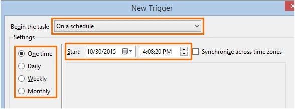
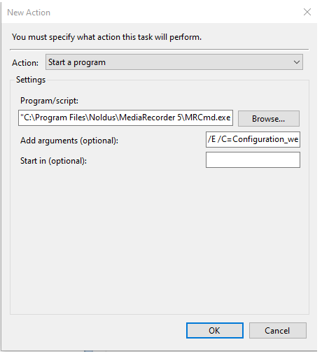
Notes
- IMPORTANT Allow enough time between the commands. If a command is sent before the previous one is carried out, the second command is not carried out. For example, if the command Start Recording is sent before MediaRecorder is completely open, recording does not start.
- By default, the tasks are stored in the folder Task Scheduler Library. To edit or delete a task, click this folder in the tree on the left side and select the task in the window Task Scheduler Library. In the Actions pane, click Properties, or Delete.
Set up Analog cameras
Set up analog cameras
Which situation applies to you?
- You ordered computer, cameras, and MediaRecorder at Noldus IT.
The video capture card is already installed in the computer. Also MediaRecorder has been set up to use with these cameras. You can connect your cameras and start recording.
See Record video
- You bought the computer and cameras somewhere else
Follow the procedure below.
Procedure
- Install the Picolo Alert PCIe card
- Install the drivers for the Picolo Alert card
- Connect the analog camera to the computer
Install the Picolo Alert PCIe card
Aim
To install the card that digitizes the output of analog cameras.
Prerequisites
- You use MediaRecorder with analog cameras.
- You did not buy a complete setup from Noldus IT. If you bought a complete setup from Noldus IT, the card has been installed in the computer., so you can skip this topic.
Procedure
- Make sure your computer is turned off and the power cable is disconnected.
- Open the computer.
- Select a free PCIe expansion slot, and remove the corresponding extension cover. See PCIe slot properties for more information on different PCIe slots in a Dell computer.
- Unpack the Euresys Picolo Alert PCIe card, place it into the slot, and press it carefully into position. If the card does not fit into place easily, remove it and repeat the operation.

IMPORTANT When touching the board, its electronic components can be damaged by static electricity. To avoid any such risk, make sure that you are grounded. You can ground yourself by putting on an earthing wristlet, and attaching its clip to the metal frame of the computer. If an earthing wristlet is not available, you can hold the metal frame with one hand while holding the Ethernet card in your other hand. Ensure also that your clothing does not touch any components while handling the card.
- Fix the card to the chassis and re-fit the computer's cover.
- Close the computer.

PCIe slot properties
Different PCIe slots have different properties, resulting in different performances. When possible, choose the slot that gives maximum performance. To estimate performance, take note of the slot version (2, 3, etc.; see the figure below). Do not use the graphic slots (see also the drawing of the available slots).
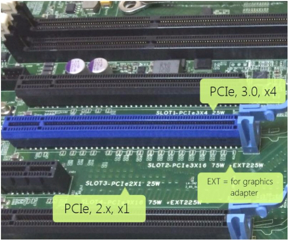
Details of the PCIe slots in a Dell computer.
Compare this number with the following table:
- PCIe v1.x: 250 MB/s
- PCIe v2.x: 500 MB/s
- PCIe v3.0: ~1 GB/s
- PCIe v4.0: ~2GB/s
Note that values are given per lane; they should not be multiplied by the number of lanes in a slot (e.g. x4) since the card has a 1x connector).
Install the drivers for the Picolo Alert card
Aim
To install the software that allows communication between the Euresys card and the computer operating systems.
Prerequisites
- You use MediaRecorder with analog cameras.
- You did not buy a complete setup from Noldus IT.
- You installed the Euresys Picolo Alert card into the computer.
Procedure
- Insert the MediaRecorder installation USB stick into your computer.
- If you have the Picolo Alert card, open the folder Drivers and Tools\Drivers\Euresys\Alert and double-click the file multicam-win10-6.15.1.3573.exe
- Follow the instructions on your screen.
- When installation is finished, a message appears that the drivers were successfully installed. Click Close.
- Installing the Picolo card drivers involves a a computer restart. After restart, the installation is finished.
Continue with installing MediaRecorder. See Installation
Connect the analog camera to the computer
important By default Windows 10 computers have the option Fast startup enabled. This means that the computer goes into standby instead of shutting down when you switch off the computer. This can sometimes cause MediaRecorder to stop responding when selecting an input of the H.264 video capture card. Therefore, for analog cameras it is especially important to select the correct power options. See Select correct power options in The steps to install MediaRecorder.
The connectors on the Picolo Alert PCIe video capture card
The Picolo Alert PCIe card has 4 BNC connectors. This card has an effective delivery bandwidth of 180MB/s.
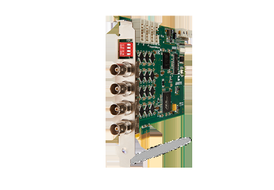
To connect the camera
If your camera has a BNC output connector, connect a coaxial cable, with BNC connectors on both sides, between Video Out of the camera and one of the BNC inputs of the breakout cable.

If your camera does not have a BNC connection, use a converter.
Change video standard
Aim
To specify the correct video standard to be used by the Picolo Alert PCIe card.
Procedure
- Open Video settings the first time you select the Picolo Alert PCIe card.

- Select the correct video standard, depending on your cameras. It’s typically PAL for Europe and NTSC for the US. You need to do this four times, selecting all four channels from the Board drop-down box (channels are numbered #0-#3). Press Apply after setting the correct Video Standard for each channel.

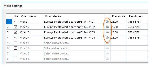
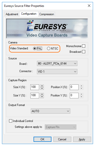
You should see the preview after setting the Video Standard correctly. Failing this will result in a black preview. You can only modify this setting the first time before the preview is running, after that it will become disabled. To be able to modify it, simply deselect the camera from the video inputs, and then select it again, to make the setting editable once more.
Set up IP cameras
Set up IP cameras
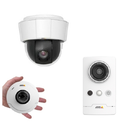
Main topics
- The steps to install IP cameras
- Ethernet card setup
- Camera setup
- Select ONVIF cameras in MediaRecorder
- Select devices that do not support ONVIF in MediaRecorder
The steps to install IP cameras
Prerequisites
- The network allows data transfer of at least 1 Gb per second.
- We recommend to use a dedicated network for the cameras.
- The cables must be suitable for Gigabit Ethernet. The minimum cable quality is CAT5e
https://en.wikipedia.org/wiki/Category_5_cable - You have Axis IP cameras that are supported with MediaRecorder.
See Supported IP cameras in Recording devices
Which situation applies to you?
- You ordered computer, IP cameras and MediaRecorder at Noldus IT
The cameras are already installed. Also MediaRecorder has been set up to use with these cameras. You can connect your cameras and start recording.
See Record video
- You bought the cameras from Noldus IT and installed MediaRecorder on your computer
The camera IP address and settings have been created by Noldus IT. Carry out the steps in procedure below, except for steps 5,6,7, and 8.:
- You bought the computer and cameras somewhere else. Carry out the entire procedure below.
Procedure
- Install the Ethernet card
- Set Ethernet card IP address
- Connect IP cameras to the PC
- Set camera IP address
- Set camera password and select power line frequency
- Create camera settings
- Create audio settings
- Select ONVIF cameras in MediaRecorder
- or
- Select devices that do not support ONVIF in MediaRecorder
Notes
- The procedures apply to Axis IP cameras. If you bought cameras from a different brand, look for comparable settings in the camera manual.
- We recommend to use Axis IP cameras since these were tested with MediaRecorder.
- The Axis cameras sold by Noldus IT support ONVIF.
Ethernet card setup
Aim
To insert the 1 Gb Ethernet card into your computer and to configure it to work with MediaRecorder.

Prerequisites
- You have IP or GigE cameras.
- You have an Intel PRO/1000 GT or Intel Pro/ 1000 PT Ethernet card.
- You purchased the computer with MediaRecorder yourself, or you bought the cameras after you received the computer.
If you bought a complete system from Noldus IT, the card has been installed and set up. You can skip this topic.
Procedure
Carry out the following steps:
Install the Ethernet card
Aim
To place the Ethernet card into the computer with MediaRecorder.
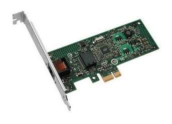
Prerequisites
- You have IP or GigE cameras.
- You have an Intel PRO/1000 GT or Intel Pro/ 1000 PT Ethernet card.
- You purchased the computer with MediaRecorder yourself, or you bought the cameras after you received the computer.
Procedure
- Turn off your computer and all connected peripherals, such as the monitor and printer. Make sure that the computer is unplugged.
- Remove the PC's case according to the instructions provided in the PC's user manual.
- Select a free PCIe expansion slot, and remove the corresponding extension cover.
See PCIe slot properties in Set up analog cameras for details in the slots in a Dell computer. - Unpack the Ethernet card, place it into the slot, and press it carefully into position. If the card does not fit into place easily, remove it and repeat the operation.
IMPORTANT When touching the board, its electronic components can be damaged by static electricity. To avoid any such risk, make sure that you are grounded. You can ground yourself by putting on an earthing wristlet, and attaching its clip to the metal frame of the computer. If an earthing wristlet is not available, you can hold the metal frame with one hand while holding the Ethernet in your other hand. Ensure also that your clothing does not touch any components while handling the card.
- Fix the card to the chassis and re-fit the computer's cover.
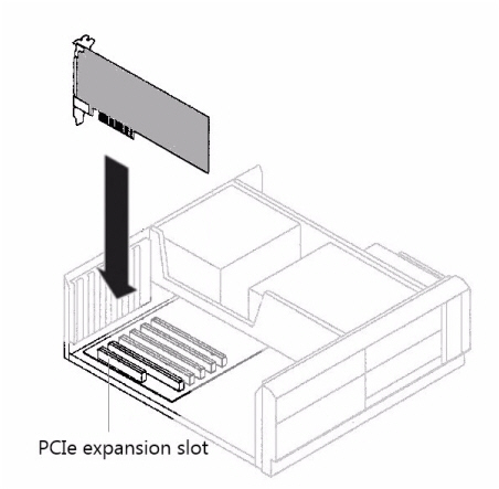
Set Ethernet card IP address
Aim
To set the IP address of the Ethernet card to the same range as the cameras and the computer.
Prerequisites
- You have IP or GigE cameras.
- You purchased the computer with MediaRecorder yourself, or you bought the cameras after you received the computer.
- You installed the Ethernet card into the computer.
See Install the Ethernet card
Procedure
- Open the Control Panel and select Network and Sharing Center.
- Click Change adapter settings on the left side of your window.

- Right-click Local Area Connection and click Properties. If your computer has more than one Local Area Connection, choose the one used for the cameras. To check which one this is, remove the cable from this IP port on your computer. The LAN connection that has the status Not connected is the correct one.

- Select Internet Protocol Version 4 (TCP/IPv4) and click Properties.

- Click Use the following IP address and enter the IP address and Subnet mask supplied by your system administrator. Leave the other fields empty. Also select the checkbox Validate settings upon exit. When done, click OK and then Close.

- A Windows Network Diagnostics window appears. Click Close when the validation is finished. Then close all windows.
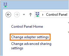
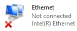
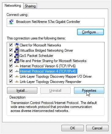
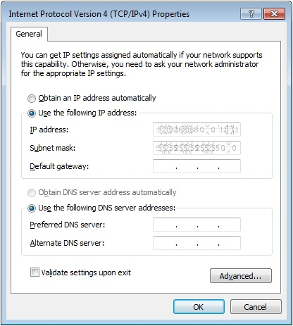
Connect IP cameras to the PC
Prerequisite
You have followed the entire procedure in Ethernet card setup
Procedure
The procedure applies to a Cisco SG 100D 8 port Gigabit PoE-switch, which is supported with MediaRecorder.
Using cross-network cables (cat-5e or newer), connect the Ethernet card on the PC to one of the four right ports of the PoE-switch.
- Connect the camera to one of the four left ports of the PoE-switch. Do not use any of the four right ports for this purpose, since they do not supply your cameras with power.
- Power up the PoE-switch.
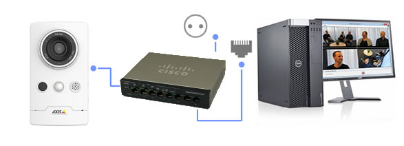
Notes
- The Power over Ethernet (PoE) switch is a device that receives and sends data (in this case, video data from the camera) and passes power along on twisted-pair Ethernet cabling.
- If you use multiple IP cameras, connect them to separate ports on the PoE-switch. Make sure the capacity of the switch is high enough for the cameras.
See Power over Ethernet in Recording devices
Camera setup
Aim
To configure the cameras for use with MediaRecorder.
Prerequisites
- You have Axis IP cameras that are supported with MediaRecorder.
See Supported IP cameras in Recording devices - You followed the procedure in Ethernet card setup
- You connected all cameras.
Procedure
You must carry out the following steps for each camera:
- Set camera IP address
- Set camera password and select power line frequency
- Create camera settings
- Create audio settings
Set camera IP address
Aim
To set the IP address of the camera to the same range as the Ethernet card and the computer.
Prerequisites
- You have Axis IP cameras that are supported with MediaRecorder.
See Supported IP cameras in Recording devices - You installed the Ethernet card.
See Install the Ethernet card
- You gave the card a fixed IP address.
See Set Ethernet card IP address
- You connected all cameras.
Procedure
- Insert the MediaRecorder installation USB stick into your computer and copy the file IPUtility.exe from the folder Drivers and Tools\Software\Axis Tools to your computer. Do not copy it to your desktop, the tool will then not work correctly.
- Run IPUtility.exe. A window opens in which all the connected devices are listed.
- Right-click the device and select Assign IP address.

- Enter the IP address and choose Assign.

- According to the message that appears, disconnect and reconnect the camera and click Assign. Wait until the IP address is set.
- Right-click the camera and select Test IP address. When the details were entered correctly a message appears that the camera is accessible.
- Repeat steps 3 to 6 for all cameras. Make sure you use different IP addresses for all cameras and computer and other network devices in the network.
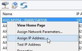
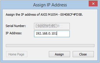
Set camera password and select power line frequency
Aim
To give the camera a password, which is compulsory, and to select the power line frequency of your country.
Prerequisites
- You have Axis IP cameras that are supported with MediaRecorder.
See Supported IP cameras in Recording devices
- You followed the procedure in Ethernet card setup
- You connected all cameras.
- You gave the cameras an IP address.
See Set camera IP address
Procedure
IP address
- In the IPUtility tool, click the Home Page button. the camera now opens in a browser.

Alternatively, type the IP address in the address field of, for example, Internet Explorer. - The first time you open the camera in a browser, you must set a password. If you obtained cameras from Noldus IT, this password is Noldus. The user name root cannot be changed. Do not use the characters @, space, or colon (:) for the password. These characters cannot be used in MediaRecorder.
- As soon as you set the password, you must log in to the camera with the password you just set.
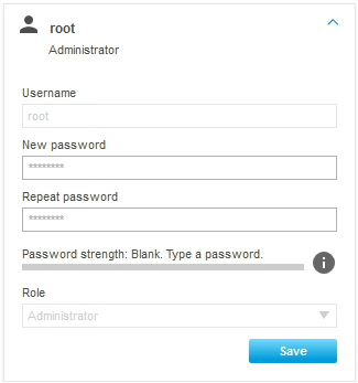

Power line frequency
The first time you log in in the camera, you must select a power line frequency. Look up the correct power line frequency of your country on Internet.
Notes
- IMPORTANT Close the browser before you start recording. Leaving it open may cause recording problems in MediaRecorder.
- If you do not get a view in Internet Explorer, click the Settings wheel in the upper-right corner of your window and choose Compatibility View Settings. Enter the IP address of your camera and click Add. Other browsers may have a comparable setting.
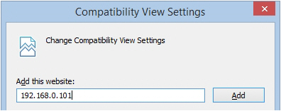
Create camera settings
Aim
To configure the camera for optimal recording with MediaRecorder.
Prerequisites
- You have Axis IP cameras that are supported with MediaRecorder.
See Supported IP cameras in Recording devices
- You installed the Ethernet card.
See Install the Ethernet card
- You gave the card a fixed IP address.
See Set Ethernet card IP address
- You connected all cameras.
- You gave the cameras an IP address.
See Set camera IP address
- You gave the camera a password and selected the correct power line frequency.
See Set camera password and select power line frequency
Procedure
Carry out the following steps:
- Access camera settings
- Create ONVIF User name and Password
- Disable replay attack protection
- Switch on IR cut filter
Note
The procedure below describes the camera firmware version 7.20.1. For other firmware versions, search for comparable settings.
Access camera settings
- Open the camera in a browser by clicking the Home page button in the IPUtility tool or typing the IP address in the address field of an Internet browser. Then enter the password.
- Click the Settings button in the bottom-right corner of your window.
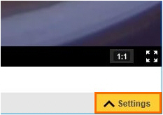
Create ONVIF User name and Password
Aim
To configure the camera so that pan, tilt, zoom, and audio recording is possible.
Procedure
- Open the camera settings.
- Open the System tab and click ONVIF.

- Click Add and enter the same User name and Password as set in Set camera password and select power line frequency. Do not use the characters @, space, or colon (:) for the user name or password. These characters cannot be used in MediaRecorder.
- Select Administrator as User Group and click OK.

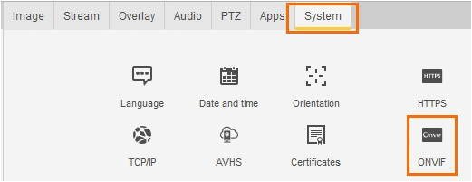
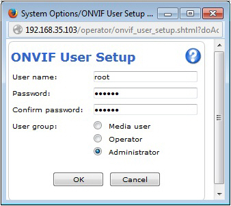
Notes
- If the camera does not support ONVIF, pan, tilt, and zoom must be done with a browser and audio of the camera cannot be recorded. All IP cameras supported with MediaRecorder support ONVIF.
- IMPORTANT Always close the browser before you start recording with MediaRecorder.
Disable replay attack protection
Aim
To prevent that connection to the camera fails if the time of the MediaRecorder computer differs from the time in the camera.
Background
Replay attack protection is a camera security setting. Relevant for video recording with MediaRecorder is that replay attack protection causes the camera connection to fail if the timestamps of MediaRecorder and the camera are not exactly the same. Replay attack protection is necessary for security cameras, but not for IP cameras in a dedicated network.
Procedure
- Open the camera settings.
See Access camera settings - Open the System tab and click Plain config.
- From the list at the bottom, select WebService and click Select Group.
- Under WebService UsernameToken:, make sure the checkbox Enable replay attack protection is not selected.
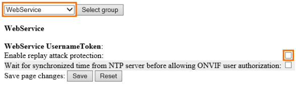
Note
If you do not want to disable this option, make sure that the clock times of the computer and camera are exactly the same.
Switch on IR cut filter
Aim
To make sure the cameras does not switch to black and white at low light levels.
Background
The IR cut filter removes infrared light during daylight. With the default camera settings, the IR cut filter is switched off at low light intensities. The camera then records in near-infrared, which gives a black and white camera image. If you do not want this, set the IR cut filter to On instead of Auto, so that it stays on, independent of the light level.
Procedure
- Open the camera settings.
- Open the Image tab.
- Check if there is an option IR cut filter. If so, set it to On.
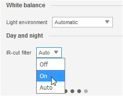
Note
Not all IP cameras supported with MediaRecorder have an IR cut filter.
Create audio settings
Aim
To optimize the recording volume.
Prerequisites
- You have Axis IP cameras that are supported with MediaRecorder.
See Supported IP cameras in Recording devices - You followed the procedure in Ethernet card setup
- You connected all cameras.
- You gave the cameras an IP address.
See Set camera IP address
- You gave the camera a password and selected the correct power line frequency.
See Set camera password and select power line frequency
- You followed the procedure in Create camera settings
Procedure
- Open the camera settings,
See Access camera settings - Open the Audio tab.
- Adjust the Gain slider and check in the Input section that the green field in the Level field is maximal with normal speech.

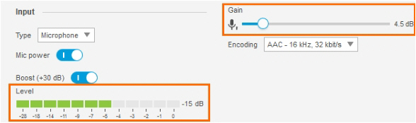
Note
You cannot record the audio of non-ONVIF devices in MediaRecorder. Optionally record audio from a separate microphone that is connected to the microphone input of the computer with MediaRecorder. The Axis cameras supported with MediaRecorder support ONVIF.
Select ONVIF cameras in MediaRecorder
Aim
To select a camera that supports ONVIF Profile S in MediaRecorder.
If your device does not support ONVIF, see Select devices that do not support ONVIF in MediaRecorder instead.
Prerequisites
- You have Axis IP cameras that are supported with MediaRecorder.
See Supported IP cameras in Recording devices
- You followed the procedure in Ethernet card setup
- You followed the procedure in Camera setup
- You installed MediaRecorder
See Installation
- You connected all cameras to the computer with MediaRecorder.
Procedure
- Open MediaRecorder and choose File > Video Settings or click Video Settings.
- Select the checkbox in front of the video channel and choose RTSP IP Camera (Noldus RTSP Source Filter).

- Click the Advanced Video Settings button.

- A list with ONVIF cameras in the network appears. Select the camera.
- Enter the ONVIF User name and ONVIF Password for your camera. If you obtained cameras from Noldus IT, the ONVIF user name is root and the ONVIF password is Noldus.
TIP To select another camera, click the Discover button to display the list with ONVIF cameras in the network.
TIP If you have several cameras with the same ONVIF User name and ONVIF Password choose File > Preferences > IP camera settings. Select Use default IP camera user name and password and enter the credentials. You can now skip step 5 and 6, the camera is detected automatically. - Click Get device properties.

- The Encoding and Quality fields appears with the default video format, frame rate and resolution of the camera.

- Optionally, click Edit and select another frame rate or resolution. Click Update when done.
For low frame rate recordings, it is important to lower the H264 Gov length too on the same screen, under Advanced settings. For 5 fps, set the Gov length between 5 and 10, for 1 fps recording between 1 and 2. A lower Gov length will result in larger files but better image.
TIP It is also possible to change the frame rate and resolution in the table with selected video devices.
You may still need to adjust the Gov length for optimal results. - Optionally, adjust the video quality, for example to decrease the video file size, but we recommend to only do this when problems with video quality or data transfer over the network occur.
See Adjust advanced video quality options - .Click Close when done.
- You may want to reverse the direction the camera moves with Pan and Tilt). To do so, select the checkbox Flip pan axis (horizontal movement) or Flip tilt axis (vertical movement) or both.

- Click OK.
- Select the microphone from the Audio device list. To select the microphone from the camera, or a microphone connected to it, select RTSP IP camera (Noldus RTSP Source Filter) from the Audio device list.
- Close the Settings window and tap on the microphone. Check the green bar next to the video device to see whether you selected the correct microphone.
- Continue with Record video

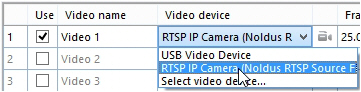
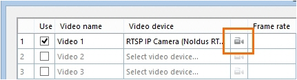
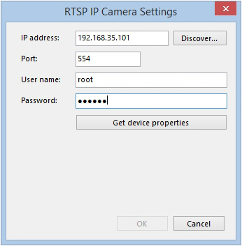

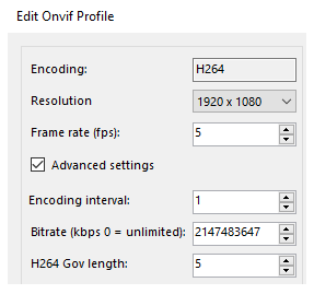
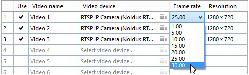
Notes
- If you bought cameras yourself, see Create ONVIF User name and Password for the procedure to create an ONVIF user name and ONVIF password.
- If the default Port 554 is already in use, ask your system administrator for help to select another one.
- See Create audio settings how to adjust the recording volume.
Adjust advanced video quality options
Aim
To change video quality, for example to reduce the video file size.
Prerequisite
You experience problems with video quality or data transfer over the network. In all other cases, we recommend not to change the default settings.
Procedure
- Choose File > Video Settings or click Video settings.
- Click the Advanced Video Settings button.
- Click Get device Properties. This enables the Edit button. Click Edit.
- Select Advanced settings.
- Adjust the settings and click Update > Close.
- See Advanced video quality options for a description of the options.
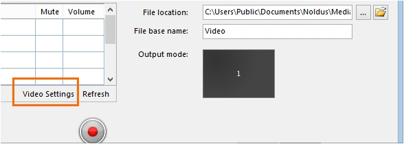

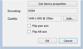
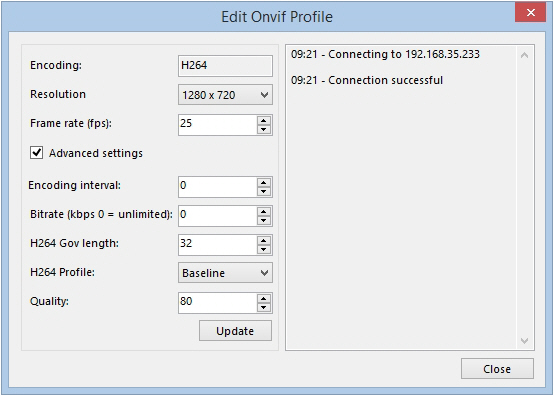
Advanced video quality options
If an option cannot be edited, your camera does not support other options, or the value is set by the chosen profile.
Encoding interval
This value cannot be edited and is set by the profile.
Bitrate
To set a limit to the data transfer. The default value 0 means unlimited. If you enter a value, data transfer is limited to this value in Kb per second.
H264 Gov length
The interval in which the I-Frames will be coded in the video file. A value of 1 means that every frame is an I-frame. A value of 2 means that every second frame is an I-frame. Decreasing the number increases the video quality, but also the data transfer. For a description of the frame types, see:
https://en.wikipedia.org/wiki/Video_compression_picture_types
H264 Profile
The encoding profile from the IP camera. MediaRecorder uses the Baseline profile and this option cannot be edited.
Quality
The quality of the encoded video file. Higher number gives higher encoding quality, but also more data transfer over the network.
Select devices that do not support ONVIF in MediaRecorder
Aim
To select a device that does not support ONVIF Profile S in MediaRecorder.
If your device does support ONVIF, see Select ONVIF cameras in MediaRecorder instead.
Prerequisites
- Your device does not support ONVIF Profile S
- You followed the procedure in Ethernet card setup
- You created comparable settings for you device as described in Camera setup
- You installed MediaRecorder
See Installation
- You connected your video device to the computer with MediaRecorder.
Procedure
- Open MediaRecorder and choose File > Video settings or click Video settings.
- Select the checkbox in front of the video channel and choose RTSP IP Camera (Noldus RTSP Source Filter).
- Click the Advanced Video Settings button.
- A list with available ONVIF cameras in the network appears.
IMPORTANT If your device does not support ONVIF, it will not be on this list. Click Cancel.
- Enter the IP address, User name and Password of the device. If you bought your device from Noldus IT, the User name is root and the Password is Noldus.
If the default Port 554 is already in use, ask your system administrator for help to select another one. - Click Get device properties.

- The field Connection string appears.

- Look up in the manual of your device where the video files can be accessed via the RTSP communication protocol. Enter the path from the slash after the connection information in the Connection string field. For example,
/stream.sdp for an Epiphan Pearl Nano screen capture device/.
- Click OK. Optionally, select another frame rate or resolution. However, make sure you select the same frame rate as is selected in the device itself when you opened the camera in a browser (see the next step).
- Optionally, open the camera in a browser to pan, tilt, or zoom.
See Access camera settings


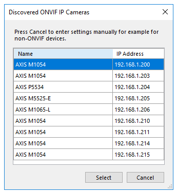
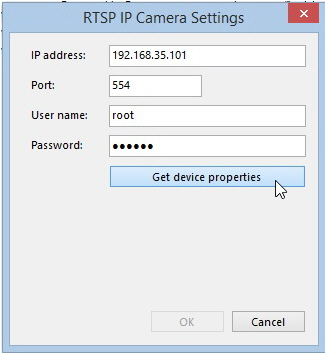
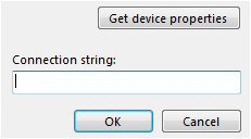
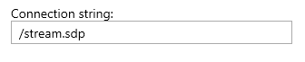
IMPORTANT Close the browser before starting recording with MediaRecorder.
- Click OK and continue with Record video
Set up GigE cameras
Set up GigE cameras
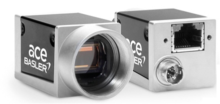
Main topics
- The steps to install GigE cameras
- Connect the GigE cameras to the PC
- Install MediaRecorder with the camera drivers
- Set camera IP address
- Configure the cameras
The steps to install GigE cameras
Prerequisites
- The network allows data transfer of at least 1 Gb per second.
- We recommend to use a dedicated network for the cameras.
- The cables must be suitable for Gigabit Ethernet. The minimum cable quality is CAT5e.
https://en.wikipedia.org/wiki/Category_5_cable
- You have GigE cameras that are supported with MediaRecorder.
See Supported GigE camera in Recording devices
Which situation applies to you?
- You bought the computer, cameras and MediaRecorder from Noldus IT.
The cameras are already installed. Also MediaRecorder has been set up to use with these cameras. Connect the cameras to the computer and start recording.
See Connect the GigE cameras to the PC and Record video
- You bought the cameras from Noldus IT and installed MediaRecorder on your own computer
The camera IP address has been set and the cameras are configured.
Carry out the Procedure below but skip steps 6 and 7.
- You bought the computer and cameras somewhere else.
Carry out the Procedure below.
Procedure
- Install the Ethernet card. This is the same procedure as for IP cameras.
See Install the Ethernet card in Set up IP cameras.
To record from multiple cameras you can use a 4-port PCIe board. MediaRecorder has been tested with the Adlink PCIe-GIE74 Ethernet board.
If you use an Adlink PCIe-GIE74 board make sure the board receives power from the PC. Connect the power connector on the board (Molex/IDE male 4-pin DC) to one of the power supplies inside the PC. Connector types vary between computers. Many computers have a SATA 15-pin power connector. Use an adapter cable with a 4-pin female Molex connector at one end and a SATA 15-pin connector at the other end.
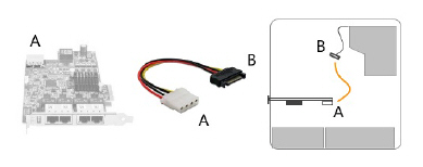
- Give the Ethernet card a fixed IP address. This is the same procedure as for IP cameras.
See Set Ethernet card IP address in Set up IP cameras - Connect the camera to the computer with MediaRecorder.
See Connect the GigE cameras to the PC - Carry out the prerequisite steps before installing MediaRecorder.
See The steps to install MediaRecorder in Installation - Install MediaRecorder with the camera drivers
- Set camera IP address
- Configure the cameras
I bought the cameras from Noldus IT and istalled MediaRecorder on my computer
You must carry out the following steps:
- Install the Ethernet card. This is the same procedure as for IP cameras.
See Install the Ethernet card in Set up IP cameras
If you use an Adlink PCIe-GIE74 board make sure the board receives power from the PC.
- Give the Ethernet card a fixed IP address. This is the same procedure as for IP cameras.
See Set Ethernet card IP address in Set up IP cameras - Connect the camera to the computer with MediaRecorder.
See Connect the GigE cameras to the PC - Carry out the prerequisite steps before installing MediaRecorder.
See The steps to install MediaRecorder in Installation - Install MediaRecorder with the camera drivers
Connect the GigE cameras to the PC
Prerequisite
- You have followed the entire procedure in Ethernet card setup in Set up IP cameras
- No matter how many cameras you use, you need a 1Gb Ethernet interface board (desktop computers only).
- When you use a 4-port Ethernet board, you can power the cameras with Power-over-Ethernet (PoE) injectors but you can also choose to connect the board to the power outlet inside the PC. See Power over Ethernet in GigE Vision cameras.
- You must use a 1-Gb Power-over-Ethernet (PoE) injector when the PC does not have a 4-port Ethernet board. Use one PoE injector per camera.
- Cables: Use Cat5e or Cat6e crossover cables.
- Do not use an Ethernet to USB adapter (in the picture below) to connect the camera to the PC. Always connect the camera and the PC directly using an Ethernet crossover cable.
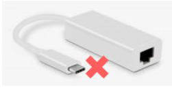
Procedure
- Using cross-network cables (cat-5e or newer), connect the Ethernet card on the PC to the IN port of the PoE-injector. Connect the camera to the OUT port. Use the short cable between PoE-injector and PC. Use the long cable between PoE-injector and camera.
- Power up the PoE-injector; make sure that the two CONNECT and ON green LEDs are on.
If the green LEDs keep blinking, wait a few more seconds. If you see no change, disconnect the cables, then re-connect them.
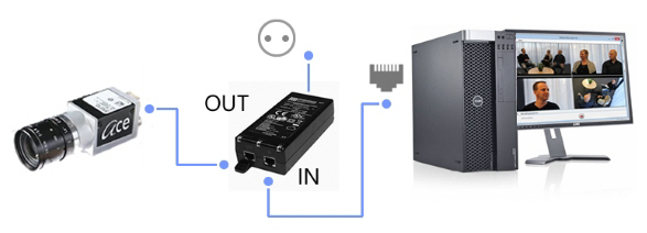
Notes
- The Power over Ethernet (PoE) injector is a device that passes power along with data (in this case, video data from the camera) via twisted-pair Ethernet cabling.
- If you have multiple cameras in combination with a 4-port Adlink PCIe-GIE74 board, make sure to connect the cameras one by one and assign an IP address to the camera before you connect the next camera. It is important that each camera is always connected to the same port on the Ethernet board. Each port is viewed as a network adapter, with its own IP address. The information of the linked port is stored in the driver software of each camera. If you swap cameras, they will not be recognized. Therefore, always label the Ethernet ports and the cameras.
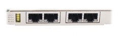
Install MediaRecorder with the camera drivers
Aim
To install the software that allows communication between your camera and the operating system of the computer with MediaRecorder.
Prerequisites
- You installed the Ethernet card.
See Install the Ethernet card in Set up IP cameras
- You gave the Ethernet card a fixed IP address.
See Set Ethernet card IP address in Set up IP cameras
- You carried out the prerequisite steps before installing MediaRecorder.
See The steps to install MediaRecorder in Installation
Procedure
important If you upgraded from a previous MediaRecorder version and have old drivers for the camera installed, uninstall them first.
If you did not yet install MediaRecorder
- Download the installation files from my.noldus.com, and extract the contents.
- Browse to the file MediaRecorder 6 Setup.exe and double-click it.
- In the Drivers and tools field, choose Basler GigE Camera driver - pylon [version number].
- Click Next, accept the License Agreement and click Install.
If you already installed MediaRecorder
Follow the instructions in If you did not yet install MediaRecorder and choose Modify in the installation window. Select Basler GigE Camera driver - pylon [version number] and click Update.
Alternatively:
- Download the installation files from my.noldus.com.
- Browse to Drivers\Basler\5.0.9.10388
- Double-click the file Basler_pylon_5.0.9.10388.
- Agree to the terms in the License Agreement.
- In the Profiles window, choose Camera user and click Next.
- As camera type, choose GigE and click Next.

- Optionally, change the location where the camera drivers are stored and choose Next > Install.
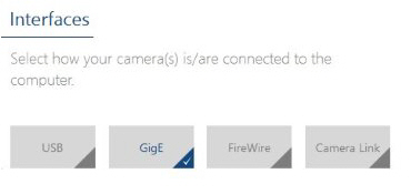
To uninstall old drivers
- Open the Control Panel
- Choose Program and Features.
- Select the Basler camera driver and choose Uninstall.
Set camera IP address
Aim
To make sure that the IP address of the GigE camera and that Ethernet interface board physically connected to that camera match. This ensures reliable data transfer to and from the camera.
Prerequisites
- You followed the procedure in Ethernet card setup
- You connected the camera. This is the same procedure as connecting an IP camera.
See Connect IP cameras to the PC in Set up IP cameras
Procedure
- 1.Double-click the Pylon IP Configuration tool icon on the desktop.

- Select the camera under Local Area Connection.

- Fill in the IP Address and Subnet Mask fields under Static IP Address as supplied by your system administrator.

- Click Save and then Close.
- If you have multiple cameras, connect the next one and repeat the steps above.

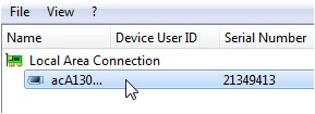
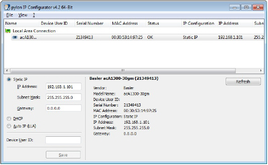
Note
Your cameras should have the same Firmware version. Check this in the Pylon Viewer software. In the Features panel, under Device Information, check Firmware Version. If the cameras do not have the same firmware, an upgrade/downgrade must be done.
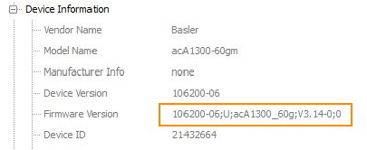
Configure the cameras
Aim
To adjust settings in a Basler GigE camera or USB 3.0 camera, like the video frame rate, video frame resolution, and exposure time, within the camera software.
NOTE Settings are stored in the camera software, not on the PC. When you work with multiple cameras, repeat the procedure for each camera.
Procedure (general)
- Make sure MediaRecorder (and EthoVision XT, when present on the computer) is not running.
- Start the Basler Pylon Viewer software that comes with the GigE cameras.
NOTE The Basler Pylon Viewer software is installed automatically when you install the camera drivers.
- In the Devices panel, under GigE, double-click the Basler camera.
- To preview the camera image, click the Continuous Shot button on the toolbar.
NOTE To be able to adjust the settings, click the Stop button first.

- Follow the instructions below that apply.

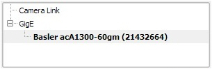 `
`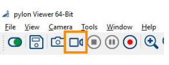
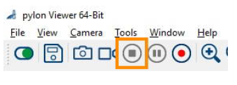
To center the camera view
With this procedure you make sure the camera view is centered.
IMPORTANT If you center the camera view in MediaRecorder, the settings may not be stored in the camera drivers. Here in Pylon viewer you make sure that the settings are stored in the drivers, also for future recordings.
- In the Features panel, open the Basler camera item and then the AOI Controls item (Image Format Control for USB 3 cameras).
- Select both options Center X and Center Y.

- Save the settings.
See To save the camera settings
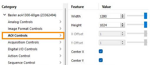
To set the pixel format
NOTE This option applies to black and white digital cameras.
- In the Features panel, open the Basler camera item and then double-click Image Format Controls.
- Set the Pixel Format to Mono 8.
- Save the settings.
See To save the camera settings
IMPORTANT This corresponds to the option Y800 in MediaRecorder. In Pylon viewer you make sure that the settings are stored in the drivers, also for future recordings.
To adjust the camera exposure time
The exposure time (or shutter time) is the time the camera shutter is kept open to let light in. The exposure time limits the maximum achievable frame rate. If the sum of the exposure time and the time needed for reading the chip (readout time) is greater than the time between consecutive video frames, the next frame may be dropped, resulting in a lower frame rate, and missed samples during tracking.
To adjust camera exposure that matches a frame rate:
- In the Features panel, open the Basler camera item and then double-click Acquisition Controls.
- Make sure that Exposure mode is Timed, and Exposure Auto is Off.
- Next to Exposure Time (Abs) [us], enter the exposure time you require, in microseconds.
For Zebrafish larvae, enter 4000 or 2000, depending on the video resolution chosen.
In all other cases, you may choose a higher value. For rodents a value below 20000 is fine. Faster animals require shorter exposure times.
Press Tab or click another field to confirm. - To check that the exposure time is compatible with your frame rate, click the Continuous Shot button on the toolbar.
At the bottom of the live video window, locate the frame rate resulting with the new exposure time. This should be the same as the one next to Acquisition Frame Rate (Abs) [Hz].

If the resulting frame rate is lower than Acquisition Frame Rate (Abs) [Hz], then either lower the exposure time (this will make the video image darker; open the lens diaphragm to compensate for this), or lower the video resolution. Do this until you see the expected frame rate.

- Save the settings.
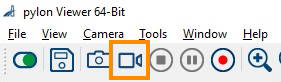
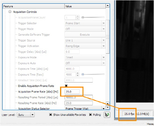
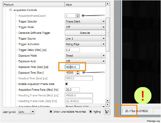
See To save the camera settings
To adjust the camera gain
This applies to both color and black/white Basler cameras.
IMPORTANT Increasing gain also increase image noise. Do this only if no other option is left to improve the image brightness. For example, make sure that the lens aperture is maximal, and increase lighting.
- In the Features panel, click Analog Controls.
- From the Gain Auto list, select Off.
- Next to Gain (Raw) (Gain [dB] for USB 3.0 cameras), select the value you require. A higher Gain results in a brighter image, but also more noise and a grainy image.

-
Save the settings.
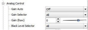
See To save the camera settings
If you have a color camera, you also need to adjust its white balance.
- Click Color Improvements Control.

- Point the camera at a piece of white paper, so that the camera image is entirely white. Click in the field next to Balance White Auto and select Once from the list.

- Save the settings (see below).
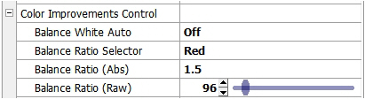
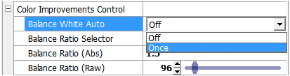
To save the camera settings
- Click the Stop button.

- In the Features panel, open the Configuration Sets item (User Set Control for USB 3 cameras).
- From the Configuration Set Selector list (User Set Selector for USB 3 cameras), select User Set 1.
- Next to User Set Save, click Execute. The camera settings set in the previous steps are now saved under User Set 1.
- From the Default Startup Set list (User Set Default for USB 3 cameras), select User Set 1.
For GigE cameras:

For USB 3 cameras:

- Close Pylon Viewer.

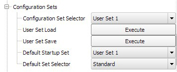
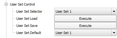
These settings will be used each time you start up MediaRecorder.
TIP You can also save different settings for the same camera in User Set 2 and User Set 3. Under Default Startup Set (User Set Default), select which you want MediaRecorder to use.
Set up the Epiphan Pearl Nano screen capture device
Set up the Epiphan Pearl Nano screen capture device
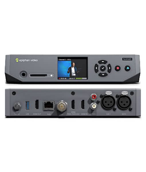
Aim
To connect the Epiphan Pearl Nano screen capture device and make the necessary settings.
Prerequisites
,
- The network allows data transfer of at least 1 Gb per second.
- We recommend to use a dedicated network for the cameras.
- The cables must be suitable for Gigabit Ethernet. The minimum cable quality is CAT5e
https://en.wikipedia.org/wiki/Category_5_cable
Procedure
- Install MediaRecorder with its prerequisites.
See Installation - Using a HDMI cable, connect the output of the video source to the HDMI IN port on the back panel of the Epiphan Pearl Nano device.

- Using a HDMI cable, connect the control monitor to the HDMI PASS THROUGH port on the back panel of the Epiphan Pearl Nano device.

- Use the control keys on the front panel to configure the system parameters.

- Using the right arrow key, navigate to System Status.

- Here, you can get the network IP address of your device and you can also check the firmware version. It is recommended to use the latest firmware version. If you need an update, register you device at Epiphan (https://www.epiphan.com/support/product-registration/)
- Using the left arrow key, navigate to Menu. Within Menu, navigate to System > Network.

- Disable DHCP. Set IP address manually. Define an IP address range similar to that of the other cameras.
- By default, do not change Network mask and Network gateway settings. If uncertain, consult your system administrator.
- Open your internet browser. Use the IP address of your Epiphan Pearl Nano device to access the Pearl Admin panel. For this, include /admin to access the Admin panel.

- Using the Pearl Admin panel, configure video encoding. Go to Channel(s), select your channel and click Encoding. In Video settings, make sure Current signal resolution is used as frame size (have the checkbox checked).

- Set Key frame interval to 1/2 sec. At Limit frame rate, it is not recommended to change the default value 30. If you use a higher frame rate, it might jeopardize your recording operation. Please do not change the default Bitrate value (auto).
- Open MediaRecorder and choose File > Video settings or click Video settings.
- In Video Settings, select the option RTSP IP Camera (Noldus RTSP Source Filter). Please note that the Epiphan Pearl Nano device is NOT an ONVIF device! For the details, see Select devices that do not support ONVIF in MediaRecorder. Please note that the RTSP connection string for this device is /stream.sdp
- Please note that you cannot use the Epiphan Pearl Nano device to make audio recordings! Use another audio device for the purpose. For the details, see Select an audio device.
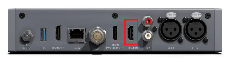

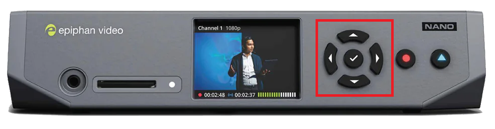
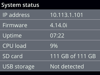
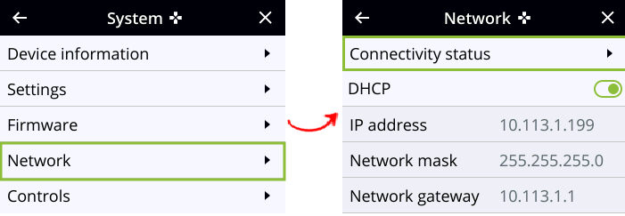

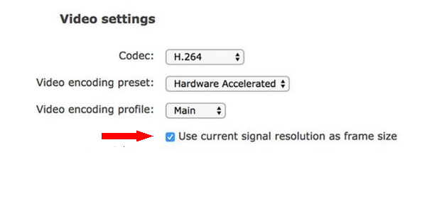
Set up USB 3 cameras
Set up USB 3 cameras
Main topics
- The steps to install USB 3 cameras
- Install the USB 3 interface card
- Install the USB 3 camera driver
- Connect the USB 3 cameras to the PC
- Configure the Basler USB 3 camera
The steps to install USB 3 cameras
Prerequisite
You have USB 3 cameras that supported with MediaRecorder.
See Supported USB cameras in Recording devices
Which situation applies to you?
- You ordered the computer, cameras and MediaRecorder from Noldus IT.
In case of Basler USB 3.0 cameras, your computer has a USB 3 card and its drivers are installed. The cameras are configured. Also MediaRecorder has been set up to use with these cameras. You can connect your cameras and start recording.
See Connect the USB 3 cameras to the PC and Record video
- You bought the computer somewhere else.
Carry out the entire Procedure below.
Procedure
- In case of Basler USB 3 cameras, install the supported USB 3 interface card, even if your computer already has USB 3 ports.
See Install the USB 3 interface card - Carry out the prerequisite steps before installing MediaRecorder.
See The steps to install MediaRecorder in Installation - Install (MediaRecorder with) the camera driver. Installing the camera driver is only needed for the Basler USB 3 camera. For the Logitech BRIO no driver installation is needed.
See Install the USB 3 camera driver - Connect the USB 3 cameras to the PC
- Configure the Basler USB 3 camera
See also
Supported USB cameras in Recording devices
Install the USB 3 interface card
MediaRecorder was tested with the following USB 3 interface cards:
- U3-PCIE1XG205 -1S - You can connect one USB 3 camera to this card.
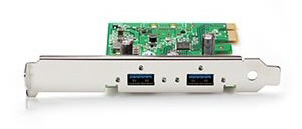
- Fresco Logic U3X4-PCIE4XE111 rev 1.1 - You can connect up to four USB 3 cameras to this board.
To install the USB 3 interface card
- Turn off your computer and all connected peripherals, such as the monitor and printer. Make sure that the computer is unplugged.
- Remove the PC's case according to the instructions provided in the PC's user manual.
- Select a free PCIe expansion slot, and remove the corresponding extension cover. For details about PCIe slots, see PCIe slot properties in Set up analog cameras
- Unpack the USB 3 interface card, place it into the slot, and press it carefully into position. If the card does not fit into place easily, remove it and repeat the operation.
- Fix the card to the chassis and re-fit the computer's cover.
If you have a 4-port Fresco Logic U3X4-PCIE4XE111 rev 1.1 board, make sure the board receives power from the PC. Connect the power connector on the board (Molex/IDE male 4-pin DC) to one of the power supplies inside the PC. Connector types vary between computers. Many computers have a SATA 15-pin power connector. Use an adapter cable with a 4-pin female Molex connector at one end and a SATA 15-pin connector at the other end.

Install the USB 3 camera driver
Aim
To install the software that allows communication between your camera and the operating system of the computer with MediaRecorder.
Prerequisites
- You have the Basler USB 3 camera.
- You have installed the USB 3 interface card.
See Install the USB 3 interface card
- You carried out the prerequisite steps before installing MediaRecorder.
See The steps to install MediaRecorder in Installation
- IMPORTANT If you upgraded from a previous MediaRecorder version and had old drivers for the camera installed, you uninstalled them first.
To uninstall old drivers
- Open the Control Panel
- Choose Program and Features.
- Select Pylon Camera Software Suite and choose Uninstall.
Install the camera drivers for the Basler USB 3 camera
If you did not yet install MediaRecorder
- Download the installation files from my.noldus.com, and extract the contents.
- Browse to the file MediaRecorder 6 Setup.exe and double-click it.
- In the Drivers and tools field, choose Basler USB Camera driver - pylon [version number].
- Click Next, accept the License Agreement and click Install.
If you already installed MediaRecorder
Follow the instructions in If you did not yet install MediaRecorder and choose Modify in the installation window.
Alternatively:
- Download the necessary files from my.noldus.nl and extract the contents.
- Browse to Drivers\Basler\7.1.0.25066
- Double-click the file Basler_pylon_7.1.0.25066.exe
. - Agree to the terms in the License Agreement.
- In the Profiles window, choose Camera user and click Next.
- As camera type, choose USB and click Next.

- Optionally, change the location where the camera drivers are stored and choose Next > Install.
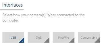
To uninstall old drivers
- Open the Control Panel
- Choose Program and Features.
- Select the Basler camera driver and choose Uninstall.
Connect the USB 3 cameras to the PC
Connect the cameras to the USB 3 interface card of the MediaRecorder computer.
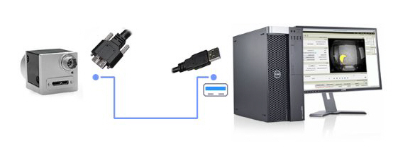
TIP USB 3 connectors and ports can be recognized by their blue color coding.
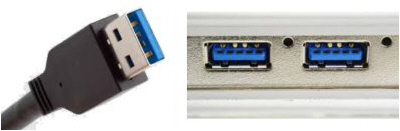
Or by a double-S in front of the USB icon.

Important note
- Using multiple Basler USB 3 cameras with a laptop is not supported.
Configure the Basler USB 3 camera
Aim
To adjust settings in the USB 3 camera, like the video frame rate, resolution, and exposure.
NOTE The camera settings are stored by the camera itself, not on the PC. When you work with multiple cameras, repeat the procedure for each camera.
Procedure
1. Make sure MediaRecorder (and EthoVision XT, when present on the computer) are not running.
2. Start the Basler Pylon Viewer software that comes with the USB 3 camera.
![]()
NOTE The Basler Pylon Viewer software is installed automatically when you install the camera drivers.
3. In the Devices panel, under USB, double-click the Basler camera.
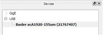
4. Under Features, open the item Basler acA1920-155um and choose the settings you would like to change. For details, see the corresponding settings in Configure the cameras in Set up GigE cameras.
5. Save the settings under User Set Control.
See also
Audio devices
Audio devices
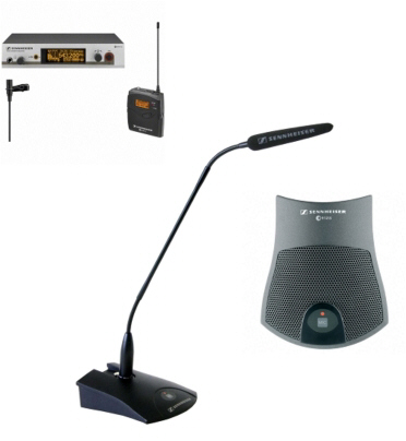
Main topics
Which audio device should I use?
The appropriate audio device depends on your setup. Take the following rules of thumb into account:
- For room settings, use one omnidirectional ceiling microphone.
- For meetings around a table, use one boundary layer table microphone.
- For usability research behind the computer, use a microphone close to the test participant, for example a wireless microphone or boundary layer table microphone.
- For very good audio quality for more than one test-participant, use a wireless microphone for each person.
- Audio quality strongly depends on the room settings. An expensive audio device does not by itself guarantee good audio. If the devices are not placed correctly, or if the acoustics in the room is bad, audio quality will be suffer.
- Do not place the microphone cables in the vicinity of 230 V electricity cables. If you, for example, route microphone cables in electrical conduits, the electricity can interfere with the audio.
- Use sound absorbing material, like curtains, to avoid echoes on audio recordings.
Important concepts in audio
Preamplifiers
The signal from a microphone is of low voltage. This signal needs to be amplified prior to further processing, like mixing or recording. This is done with a preamplifier. The strength of the signal that is amplified this way, is called line-level. When you subsequently connect the preamplifier to the sound card of your computer, select Line in when a message pops up that a new devices is detected.
The unamplified signal is very sensitive to noise. Therefore the preamplifier should be positioned as close to the microphone as possible.
When you use a digital video device and connect the audio directly to the sound card of the computer, the sound card of the computer functions as a preamplifier. So for recordings with digital devices, you can connect the microphone directly to the computer. When a message pops up that a new device is detected, select Mic-in as input source.
Balanced cables
In professional audio, a balanced line or balanced signal pair is a transmission line consisting of two conductors of the same type. Both lines have equal impedances along their lengths and equal impedances to ground and to other circuits. Both lines are twisted together and then wrapped with a third conductor (foil or braid) that acts as a shield. Common balanced cables are cables with XLR connectors. Balanced cables are the opposite of unbalanced cables. A coaxial cable is an example of an unbalanced cable.
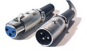
The main advantage of the use of balanced lines is good rejection of external noise. Because the signal between the microphones and preamplifier is most sensitive to noise, it is most important to use balanced lines there.
Phantom power
Phantom power, often indicated with P48, is a method to supply condenser microphones with power through microphone cables. Condenser microphones give better audio quality than other types of microphones, but they are more sensitive to noise. Preamplifiers and mixers can often supply microphones with phantom power.
Gain
The gain of a preamplifier is the degree to which the amplifier magnifies the low-level input signal compared to its output signal. It is the ratio of the output voltage divided by the input voltage and is expressed in decibels (dB). The formula to calculate gain is 20 x Log (Voltage output/Voltage input). A gain of 6 dB doubles the voltage 2 times and a gain of 20 dB gives a 10 fold increase in the signal.
Gain trim
For some amplifiers the gain can be selected in ranges. For example a LOW gain, gives a range from 18 to 38 dB. With the switch Gain trim, you can select the actual gain.
High pass filter
A high-pass filter (HPF) is a device in a preamplifier that passes high frequencies. Therefore it reduces the amplitude of frequencies lower than its cutoff frequency. It is sometimes called a low-cut filter or bass-cut filter.
Supported microphones
Ceiling microphone
Ceiling microphones are omni directional and are suitable for both speech as other sounds. MediaRecorder supports the following ceiling microphone:
Sennheiser MKE2-60-Gold-C (can also be used as table microphone)
The microphone needs 12-48V phantom power.
Table microphone
Table microphones are acoustically optimized for picking up speech. They are designed for use on conference tables, altars and lecterns. MediaRecorder supports the following table microphones:
- Sennheiser ME35
- Sennheiser ME36
- Sennheiser MKE2-60-Gold-C (can also be used as ceiling microphone)
- Sennheiser e 912 S BK
These microphones need 12-48V phantom power.
- Nikon ME-W1
Wireless microphone
MediaRecorder supports the Sennheiser EW 312 G3 B series wireless microphone set. Use this wireless microphone set when there is more than one test participant, and/or the participants are moving. The microphone set comes with a clip-on microphone and a receiver.
The wireless microphone receiver continuously switches between antennas, checks which antenna picks up the strongest signal and selects this one. This means that the antennas can be mounted at different places. If for example the reception is poor when the wireless microphone is in the experiment room, you could decide to install one antenna in this room. If the quality of the received signal is bad, for example if the signal has to go through a wall, you can use the special coax cable for extending the antennas (50Ω). In general you want both antennas to use the same cable length. It is recommended to position the two antennas at an angle of 90º.
No phantom power is needed for the wireless microphone. The signal that comes from the receiver is preamplified.
MediaRecorder also supports the Nikon ME-W1 microphone. This microphone has been tested in a portable lab set-up with a Dell 3551 notebook and Axis P1375 cameras. For more information see Recording devices.
Audio mixer
With an audio mixer you can adjust the audio streams before they go to MediaRecorder. Furthermore, you can combine the audio streams from two or more microphones. MediaRecorder supports the following audio mixers:
- Extron DMP 64
- Extron DMP 128
Summary supported devices
Summary supported devices
What information are you looking for?
- Supported devices for EthoVision XT
- Supported devices for The Observer XT - stationary set-up
- Supported devices for The Observer XT - portable set-up
- Supported devices for FaceReader
Supported devices for EthoVision XT
The table below shows the maximum supported (1) resolution, (2) frame rate (fps), (3) color space, (4) number of devices and (5) recording time (hours). All tests were carried out on a Dell Precision T3640 PC with a Euresys Picolo Alert card, card driver MultiCam 6.15.13573. When four cameras were tested in one recording, separate videos were made.
|
|
Device |
Resolution |
Frame rate |
Color space |
No of devices |
Recording time |
|
|
Ikegami B/W ICD-49 PAL |
768 x 576 |
25 |
YUY2 RGB32 |
1 |
0.5 |
|
|
Panasonic WV-CP504 NTSC |
640 x 480 |
30 |
YUY2 |
1 |
0.5 18 60 |
|
|
Analog PAL/CCIR (separate videos) |
768 x 576 |
25 |
|
4 |
24 |
|
|
Analog NTSC/EIA (separate videos) |
640 x 480 |
30 |
|
4 |
24 |
|
|
Basler USB acA1920-155um |
1920 x 1200 1920 x 1080 800 x 600 |
60 |
Y800 |
1 |
0.5 |
|
|
Basler USB acA2040-90uc* |
2040 x 2046 |
5 10 25 50 |
Y800 |
1 |
8 |
|
|
Basler acA2040-90uc* |
2040 x 2046 |
25 |
|
1 |
1 |
|
|
Basler acA2040-90uc** |
2040 x 2046 |
25 |
|
1 |
48 |
|
|
Basler acA2040-90uc (on Dell 3541 notebook) |
1920 x 1200 |
60 |
|
1 |
10 |
|
|
Basler acA1300-60gm mono |
1280 x 1024 1024 x 768 800 x 600 640 x 480 |
60 |
Y800 |
1 |
0.5 |
|
|
Basler acA1300-60gm mono |
1284 x 1025 |
25 60 |
Y800 |
1 |
8 |
|
|
Basler acA1300-60gm mono |
1280 x 1040 |
40
|
Y800 |
4
|
24 |
|
|
Basler acA1300-60gm mono |
960 x 640 |
30 60 |
Y800 |
4
|
24 |
|
|
Basler acA1300-60gm mono* |
1280 x 960 |
60 |
Y800 |
4 |
1 |
|
|
Basler acA1920-40gc color |
1920 x 1200 |
25 |
RGB32 |
1 |
18 |
|
|
Axis M1075-L |
1920 x 1080 |
25 30 |
|
1 |
16 |


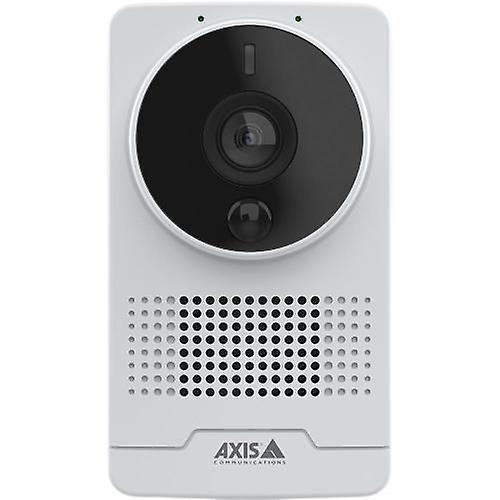
* Tested with output quality settings “EthoVision” and “DanioVision”.
** Tested with output quality setting “EthoVision”.
Important: The file size of a 8, 10, 16, 18, 24 and 60 hours recordings is very large.
Supported devices for The Observer XT - stationary set-up
The table below shows the maximum supported (1) resolution, (2) frame rate (fps), (3) number of devices and (4) recording time (hours). Tests were done on a Dell Precision T3620 PC
|
|
Device |
Resolution |
Frame rate |
Number of devices |
Recording time |
|
|
Axis M5525 (separate videos, line-in audio and camera audio*) |
1920 x 1080 |
25 30 |
4 |
3 |
|
|
Axis M5525 (Picture-by-picture & Picture-in-picture, line-in audio) |
1920 x 1080 |
30 |
4 |
3 |
|
|
Axis M5054 |
1280 x 720 |
30 |
1 |
3 |
|
|
Axis M1065-L (separate videos, line-in audio and camera audio) |
1920 x 1080 |
25 |
4 |
2 |
|
|
Axis M5525 + M1065-L (separate videos, line-in audio and camera audio) |
1920 x 1080 |
30 |
2+2 |
3 |
|
|
Axis M5525 + Epiphan Pearl Nano (separate videos, line-in audio and camera audio (broadcaster no audio)) |
1920 x 1080 |
25 |
3+1 |
3 |
|
 |
Axis M1065-L + Epiphan Pearl Nano (do NOT use Picture-in-picture or picture-by-picture) |
1920 x 1080 |
30 |
3+1 |
2 |
|
|
Axis M5525 + M1065-L + Epiphan Pearl Nano (separate videos, line-in audio and camera audio (no audio broadcaster)) |
1920 x 1080 |
30 |
1+2+1 |
3 |


* Camera audio = audio over RTSP
Supported devices for The Observer XT - portable set-up
The table below shows the maximum supported (1) resolution, (2) frame rate (fps), (3) number of devices and (4) recording time (hours). Tests were done on a Dell 3551 notebook.
|
|
Device |
Resolution |
Frame rate |
Number of devices |
Recording time |
|
|
Axis M1075-L (separate videos, line-in audio and camera audio*) |
1920 x 1080 |
25 30 |
2 |
1 |
|
|
Axis M1075-L (Picture-by-picture and Picture-in-picture, line-in audio and camera audio) |
1920 x 540 |
25 30 |
2 |
1 |
|
|
Axis M1075-L + Epiphan Pearl Nano (separate videos, line-in audio and camera audio (no audio broadcaster)) (do NOT use picture-by-picture or picture-in-picture) |
1920 x 1080 |
25 |
1+1 |
16 |
|
|
Axis P1375 + Nikon ME-W1 microphone (separate videos, picture-by-picture & picture-in-picture, camera audio only) |
1920 x 1080 |
30 |
2 |
1 |
|
|
Axis P1375 + Epiphan Pearl Nano + Nikon ME-W1 microphone (separate videos, picture-by-picture & picture-in-picture (broadcaster view in camera view), camera audio only) |
1920 x 1080 |
30 |
1+1 |
1 |
|
|
Logitech Brio* (separate videos, Picture-by-picture & Picture-in_picture, camera audio only) |
1920 x 1080 |
30 |
2 |
1 |
|
|
Logitech Brio* |
4096 x 2160 |
10 |
1 |
0.5 |
|
|
Logitech Brio* + Epiphan Pearl Nano (separate videos, Picture-by-picture & Picture-in-picture, line-in audio) |
1920 x 1080 |
30 |
1+1 |
1 |
|
|
Logitech Brio* + Epiphan Pearl Nano (separate videos, Picture-by-picture & Picture-in-picture, Logitech Brio microphone)
|
1920 x 540 |
30 |
1+1 |
1 |


* When using the Logitech Brio camera you have to change the Color space to MJPG. See Show frame rate, resolution and format.
Supported devices for FaceReader
MediaRecorder videos from all the supported devices can be analyzed by FaceReader, but the files from the individual devices have not been tested with this program.
It is important to select FaceReader RPPG as the output quality setting if you use the Remote Photo Plethysmography module in FaceReader. The recorded videos are only slightly compressed with this setting for optimal analysis of heart rate and heart rate variability.